High-temperature hearth carbonizing furnace

A carbonization furnace and furnace technology, which is applied in coke ovens, by-product vaporization, chemical instruments and methods, etc., can solve the problems of low utilization rate of carbonized by-products, not very good effect, energy waste, etc., to avoid energy gas waste, The effect of shortening carbonization time and reducing energy consumption

Inactive Publication Date: 2013-12-04
SHANDONG HONGLI HEAT PUMP ENERGY
View PDF5 Cites 7 Cited by
  • Summary
  • Abstract
  • Description
  • Claims
  • Application Information

AI Technical Summary

Problems solved by technology

In the prior art, the equipment used for sludge carbonization is a carbonization furnace. Although the carbonization furnace can solve the shortcomings of traditional sludge treatment, the carbonization furnace also has the characteristics of large investment, high energy consumption and low utilization rate of carbonization by-products.
[0004] In response to these shortcomings, some technologies that use by-products in the carbonization process as carbonization energy have also appeared in recent years, but the effect is not very good, such as: the carbonization chamber of some carbonization furnaces is placed in the combustion chamber, and holes are directly opened on the carbonization chamber The combustion of the organic matter cracking gas generated during the sludge carbonization process causes a part of the sludge to also participate in the combustion and the organic matter cracking gas cannot be fully burned and utilized; there are also carbonization furnaces with a separate combustion chamber, but the heat energy generated by the gas combustion of this type of carbonization furnace is not Being fully utilized, it is directly released into the air, causing energy waste

Method used


Image

  • High-temperature hearth carbonizing furnace
  • High-temperature hearth carbonizing furnace
  • High-temperature hearth carbonizing furnace

Examples


Embodiment Construction

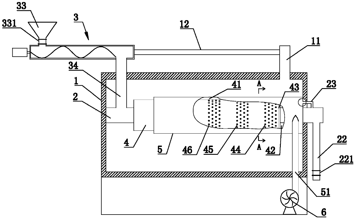
[0024] Such as figure 1 and figure 2 As shown, the high-temperature hearth carbonization furnace includes a furnace body shell 1, the space surrounded by the furnace body shell 1 is the furnace hearth, the furnace body shell 1 is provided with a smoke exhaust port 11, and the inner wall of the furnace body shell 1 is provided with silicate insulation material to avoid heat loss in the carbonization furnace.

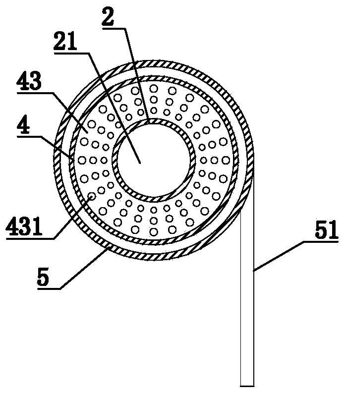
[0025] The furnace is provided with a carbonization chamber 21 surrounded by carbonization tubes 2. One end of the carbonization tube 2 protrudes from the furnace shell 1 and is provided with a carbon particle outlet 22. The furnace shell 1 is also connected with a feeding device.

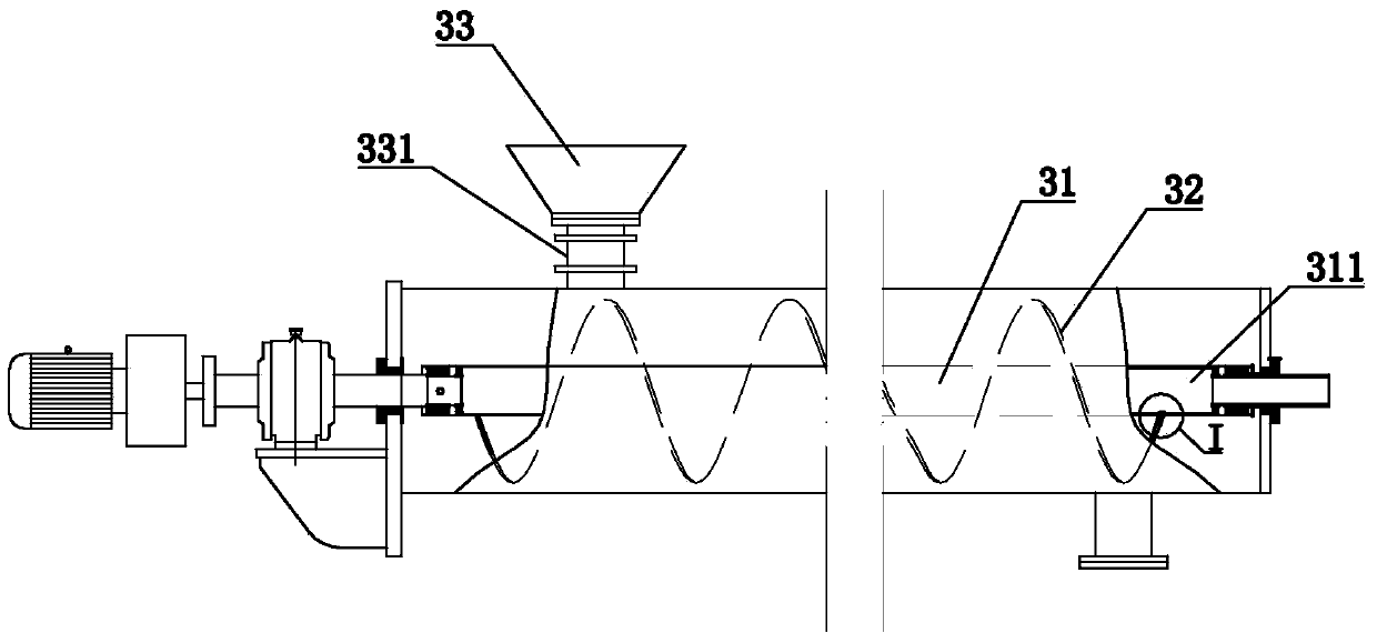
[0026] Preferably, the feeding device is a screw feeding device 3, such as image 3 and Figure 4 Commonly shown, the inside of the screw feeding device 3 is provided with a rotating shaft 31 driven by a power unit, and a screw blade 32 installed on the rotating shaft 31. The inside of the...


PUM


Abstract

The invention discloses a high-temperature hearth carbonizing furnace which comprises a furnace body casing. A carbonizing chamber is arranged in a hearth, a feeding device is further connected to the furnace body casing, the feeding device is connected with a carbonizing pipe through a feeding pipe, a combusting pipe is annularly arranged on the outer side of the carbonizing pipe, a cavity between the combusting pipe and the carbonizing pipe is divided into a combusting pipe and a pyrolysis gas distributing chamber, pyrolysis gas inlets are formed in a pyrolysis gas distributing plate, a pyrolysis gas access pipe access to the pyrolysis gas distributing chamber is arranged on the carbonizing pipe, an air pipe is annularly arranged on the outer side of the combusting chamber, and air inlets for combustion air to enter the combusting pipe are formed in the combusting pipe. The high-temperature hearth carbonizing furnace uses pyrolysis gas generated in a carbonizing process to continuously heat the carbonizing pipe, so that byproducts generated in the carbonizing process are fully utilized, waste of energy gas generated in the carbonizing process is avoided, carbonizing innocent treatment on sludge is further achieved, pollution of the sludge to the environment is avoided, energy consumption of the carbonizing furnace is reduced, and energy is saved.

Description

technical field [0001] The invention relates to the technical field of carbonization equipment, in particular to a high-temperature hearth carbonization furnace. Background technique [0002] In the prior art, sludge treatment is a necessary means to reduce the environmental pollution caused by sludge. Traditional sludge disposal methods mainly include landfill, composting and incineration. These disposal methods have some disadvantages, such as serious land occupation. , leading to potential soil and groundwater pollution, heavy metal pollution cannot be fundamentally eliminated, and pathogens and organic matter are difficult to degrade. [0003] Carbonization technology is the most thorough sludge treatment method, which can carbonize all organic matter, kill pathogens, and minimize sludge volume. In the prior art, the equipment used for sludge carbonization is a carbonization furnace. Although the carbonization furnace can solve the shortcomings of traditional sludge tre...

Claims


Application Information

Patent Timeline
Patent Type & Authority Applications(China)
IPC IPC(8): C02F11/00C02F11/10C10B53/00C10B49/02
CPCY02P20/129Y02W10/40
Inventor 赵洪明
Owner SHANDONG HONGLI HEAT PUMP ENERGY
Why Eureka
Try Eureka