Transdermal drug delivery therapeutic apparatus and transdermal drug delivery therapeutic method

A treatment method and technology of a treatment apparatus, which are applied in the field of transdermal drug delivery therapeutic apparatus and transdermal drug delivery treatment, can solve the problems of lack of engineering practicability, complex transducer structure, poor drug introduction effect, etc., and achieve automatic The effect of adapting, reducing the probability of misoperation, and reducing workload

Inactive Publication Date: 2013-12-18
曾郑刚
8 Cites 19 Cited by

AI-Extracted Technical Summary

Problems solved by technology

However, this study uses two ultrasonic transducers to work at the same time. Although it has achieved relatively good results, the structure of the two transducers used at the same time is complex, bulky, and does not have engineering practicability and cannot be used for clinical treatment.
[0019] During drug introduction, due to the complex composition of drugs, similar and diverse molecules, different molecular weights, and large structural differences, it is necessary to find out the correspond...

Abstract

The invention discloses a transdermal drug delivery therapeutic apparatus. The transdermal drug delivery therapeutic apparatus comprises a power circuit, an MCU main control module, a man-machine interaction device, an electroporation/ electricion lead-in circuit, an ultrasonic lead-in circuit and two therapeutic electrodes. The ultrasonic lead-in circuit comprises an ultrasonic oscillating circuit and a modulation circuit, wherein the signal output end of the modulation circuit is connected with the modulation signal input end of the ultrasonic oscillating circuit, and the modulation circuit is used for modulating ultrasonic signals produced by the ultrasonic oscillating circuit to obtain a plurality of ultrasonic signals with different frequencies. The invention further discloses a transdermal drug delivery therapeutic method. An ultrasonic lead-in therapeutic method includes the steps that one ultrasonic transducer corresponds to the ultrasonic oscillating circuit, and the ultrasonic signals of the ultrasonic oscillating circuit are modulated to obtain the ultrasonic signals having different frequencies and are then transmitted to the ultrasonic transducer. According to the transdermal drug delivery therapeutic apparatus and the transdermal drug delivery therapeutic method, the electroporation/ electricion lead-in drug delivery therapy and the ultrasonic wave lead-in drug delivery therapy can be conducted on a patient at the same time, therefore, a drug can be rapidly and efficiently led in the skin, and a better therapeutic effect is achieved.

Application Domain

Technology Topic

Image

  • Transdermal drug delivery therapeutic apparatus and transdermal drug delivery therapeutic method
  • Transdermal drug delivery therapeutic apparatus and transdermal drug delivery therapeutic method

Examples

  • Experimental program(1)

Example Embodiment

[0039] Below in conjunction with accompanying drawing, the present invention is described in further detail:
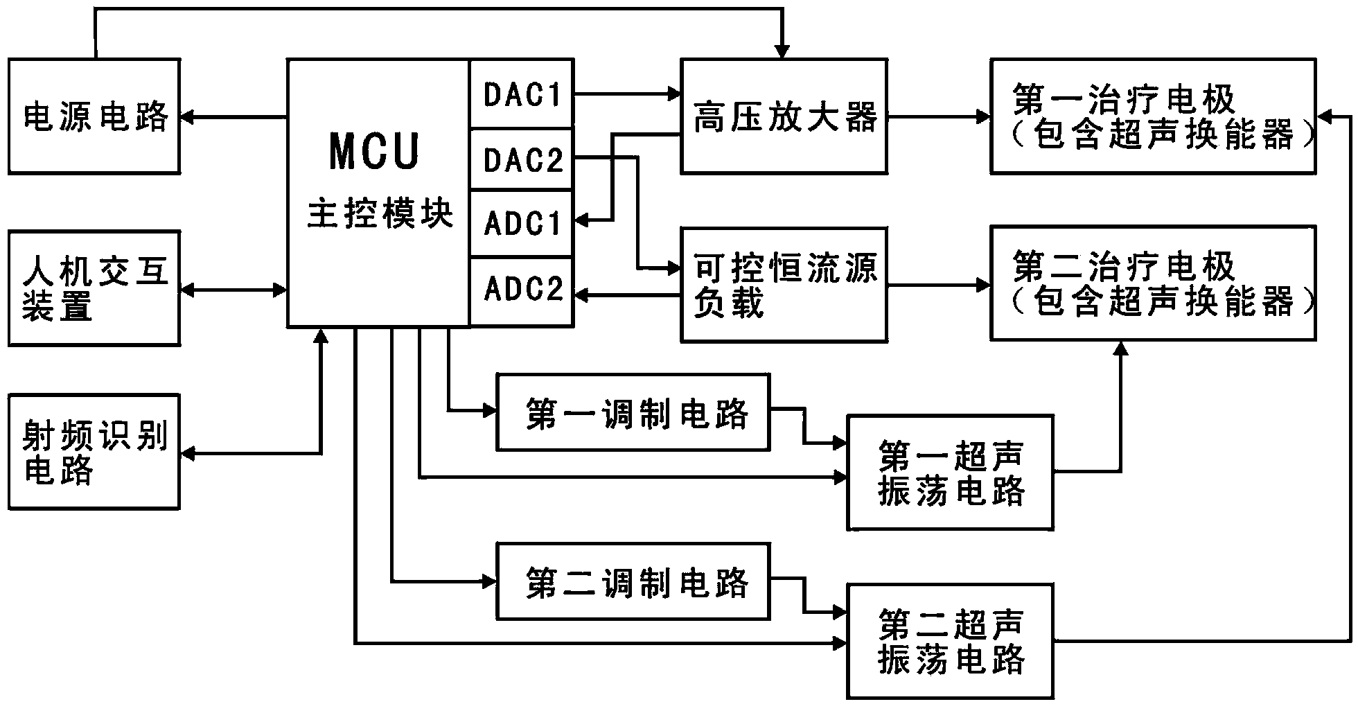
[0040] like figure 2 As shown, the transdermal drug delivery therapeutic apparatus of the present invention includes a power supply circuit, an MCU main control module, a human-computer interaction device, a first treatment electrode, a second treatment electrode, a high-voltage amplifier, a controllable constant current source load, a first modulation circuit, the second modulation circuit, the first ultrasonic oscillation circuit, the second ultrasonic oscillation circuit and the radio frequency identification circuit, the MCU main control module is provided with two DACs and two ADCs, and the two DACs are the first DAC circuit (that is, the DAC1) and the second DAC circuit (ie DAC2 in the figure), the two ADCs are the first ADC circuit (ie ADC1 in the figure) and the second ADC circuit (ie ADC2 in the figure), the signal output of the first DAC circuit The terminal is connected to the signal input terminal of the high-voltage amplifier, the signal output terminal of the second DAC circuit is connected to one terminal of the controllable constant current source load, the signal input terminal of the first ADC circuit is connected to the high-voltage amplifier, and the signal input terminal of the second ADC circuit is connected to The controllable constant current source load is connected, and the signal output end of the high-voltage amplifier and the other end of the controllable constant current source load are respectively connected to the first treatment electrode and the second treatment electrode; the first treatment electrode and the second treatment electrode both contain ultrasonic transducers. The two ultrasonic control output ends of the MCU main control module are respectively connected with the control end of the first ultrasonic oscillation circuit and the control end of the second ultrasonic oscillation circuit, and the ultrasonic signal output end of the first ultrasonic oscillation circuit and the second ultrasonic oscillation circuit are respectively connected. The ultrasonic signal output end of the circuit is respectively connected with the input end of the ultrasonic transducer of the first treatment electrode and the input end of the ultrasonic transducer of the second treatment electrode; the two modulated signal output ends of the MCU main control module are respectively connected with the first treatment electrode. The input end of the modulation circuit is connected to the input end of the second modulation circuit, and the output end of the first modulation circuit and the output end of the second modulation circuit are respectively connected with the modulation input end of the first ultrasonic oscillation circuit and the modulation input of the second ultrasonic oscillation circuit The radio frequency identification circuit is used to detect the radio frequency label information on the medicine package, and the output end of the radio frequency identification circuit is connected with the corresponding I/O terminal of the MCU main control module.
[0041] figure 2 Also shown in the power supply circuit, the power supply circuit consists of a power plug, an overcurrent protection device, a transformer, a rectifier filter circuit, and a high-voltage generator. In electroporation and iontophoresis, the highest voltage required is different. In electroporation, the highest voltage is about 200V, and iontophoresis is generally tens of V. Therefore, the power supply circuit includes a controllable high-voltage generator. It can control the output voltage of 50V or 200V. The power supply circuit is also responsible for providing the 5V and 3.3V power supplies required by the control part, and also outputs a 50V DC voltage for the ultrasonic part. The structure of the power supply circuit described above is a conventional structure.
[0042] In addition, the MCU main control module, high-voltage amplifier, controllable constant current source load and human-computer interaction device are all conventional electronic components. Among them, the MCU main control module is the control part of the whole machine. 2. It is composed of two-channel ADC. The DAC is used to generate the electrical signals required for electroporation and iontophoresis. The ADC is used to detect changes in the impedance of human skin in real time. Reference; the measurement results can be used as a reference for treatment by doctors; the high-voltage amplifier and the load of the controllable constant current source together constitute the main components of electroporation and iontophoresis. After the human skin is connected in series with the treatment electrode and the controllable constant current source, it is used as the load of the high-voltage amplifier. The human-computer interaction device is displayed by LED or LCD, and control commands are inputted by buttons (physical buttons or touch buttons).
[0043] like figure 2 As shown, when in use, the first treatment electrode and the second treatment electrode directly act on the skin of the patient, and the drug delivery and treatment method of the entire transdermal drug delivery therapeutic apparatus is as follows:
[0044] Before treatment, the optimal combination of treatment parameters for various drugs is determined through experiments, and a variety of treatment plans for different drugs are pre-made and stored in the MCU main control module.
[0045] During treatment, the radio frequency tag information (ie RFID information) on the package of the therapeutic pills is read and identified through the radio frequency identification circuit, and the MCU main control module can configure the electric power according to the drug according to the read drug information and the pre-made treatment plan. Porogenic, ionic and ultrasonic operating parameters. Operators can also configure manually.
[0046] When electroporation is introduced into the treatment, the MCU main control module controls the power supply circuit to output 200V high voltage, which is used as the power supply of the high-voltage amplifier. The required electroporation waveform is output by the two DACs in the MCU main control module. The first DAC circuit passes through the high-voltage amplifier. Amplified, it becomes 100-200V high-voltage pulse, which enters the patient's skin through the first treatment electrode and the second treatment electrode. Because its current is limited by the load of the controllable constant current source, it can avoid the damage caused by the excessive current to the patient. The control constant current source load is set by the second DAC circuit in the MCU main control module, which can output both a fixed level and a prefabricated waveform.
[0047] During iontophoresis, the MCU main control module controls the power supply circuit to output 50V, which is used as the power supply of the high-voltage amplifier.
[0048] When ultrasound is introduced into the treatment, the MCU main control module generates two ultrasonic control signals and sends them to the first ultrasonic oscillation circuit and the second ultrasonic oscillation circuit respectively, so as to generate ultrasonic signals respectively. At the same time, the MCU main control module generates two low-frequency signals. As the modulation frequency, the first modulation circuit and the second modulation circuit respectively modulate the two ultrasonic signals. The frequency of the carrier wave is determined by the resonant frequency of the ultrasound transducer itself within the treatment electrode. For an ultrasonic transducer of 1Mhz, the modulation frequency is generally tens of Khz, because the bandwidth of the ultrasonic transducer is limited. The ultrasonic signal corresponding to each of the above-mentioned treatment electrodes includes three ultrasonic signals of different frequencies, and the ultrasonic signals of multiple different frequencies are obtained by the following methods: modulate the ultrasonic oscillation with a low-frequency signal with a frequency of f2 (generated by the MCU main control module) The power supply of the circuit, the resonant frequency of the ultrasonic oscillation circuit is f1, which is a high frequency, and the envelope of the ultrasonic signal output by the ultrasonic transducer is a low frequency signal, thereby obtaining three frequencies of f1, f1+f2, and f1-f2. Ultrasound signal.
[0049] The ultrasonic transducer in the treatment electrode transmits a modulated signal, that is, three ultrasonic signals with frequencies f1, f1+f2, and f1-f2. The ultrasonic wave propagates in the human tissue, and the human tissue is nonlinear to the ultrasonic wave. The medium, due to the nonlinear effect, will generate a series of frequency doubling, difference frequency, and sum frequency, so as to demodulate f2. The new spectral component includes the f2 component, which realizes the simultaneous operation of high frequency and low frequency, and realizes a The electrode uses only one ultrasonic transducer, and conducts high and low frequency introduction at the same time.
[0050] In the above process, the skin voltage is also measured in real time through the ADC circuit in the MCU main control module, and the skin impedance is obtained through calculation, and the skin impedance is recorded and displayed for the user to evaluate the effect of promoting penetration.

PUM

no PUM

Description & Claims & Application Information

We can also present the details of the Description, Claims and Application information to help users get a comprehensive understanding of the technical details of the patent, such as background art, summary of invention, brief description of drawings, description of embodiments, and other original content. On the other hand, users can also determine the specific scope of protection of the technology through the list of claims; as well as understand the changes in the life cycle of the technology with the presentation of the patent timeline. Login to view more.

Similar technology patents

Enterogastritis oral medicine

InactiveCN101391088ANo side effectsGood treatment effectDigestive systemMolluscs material medical ingredientsCarthamusSide effect
Owner:付道成

Classification and recommendation of technical efficacy words

  • Good treatment effect
  • Improve efficiency
Why Eureka
Try Eureka