
Method and equipment for sequentially constructing ultra-long hanging posts

A construction method and technology of construction equipment, applied in construction, building structure, construction material processing and other directions, can solve problems such as large temporary support measures, affecting installation progress, increasing risk factor, etc., to achieve high installation efficiency and improve safety. , the effect of reducing the cost of construction measures

Active Publication Date: 2013-12-18
ZHEJIANG JINGGONG STEEL BUILDING GRP
View PDF5 Cites 4 Cited by
  • Summary
  • Abstract
  • Description
  • Claims
  • Application Information

AI Technical Summary

Problems solved by technology

[0005] (1) If the reverse post-installation method is used for installation, since the super-long suspender spans several floors, post-installation in sections and layers is required. This construction method not only requires a large number of temporary support measures, but also has low installation efficiency and affects installation progress;
[0006] (2) If the temporary support method is adopted for installation along the way, the risk factor of temporary support erection and dismantling at high altitudes will be greatly increased, and at the same time, the unloading of the davit will become a difficult project

Method used


Image

  • Method and equipment for sequentially constructing ultra-long hanging posts
  • Method and equipment for sequentially constructing ultra-long hanging posts
  • Method and equipment for sequentially constructing ultra-long hanging posts

Examples


Embodiment Construction

[0036] The preferred embodiments of the present invention will be described in further detail in conjunction with the accompanying drawings.

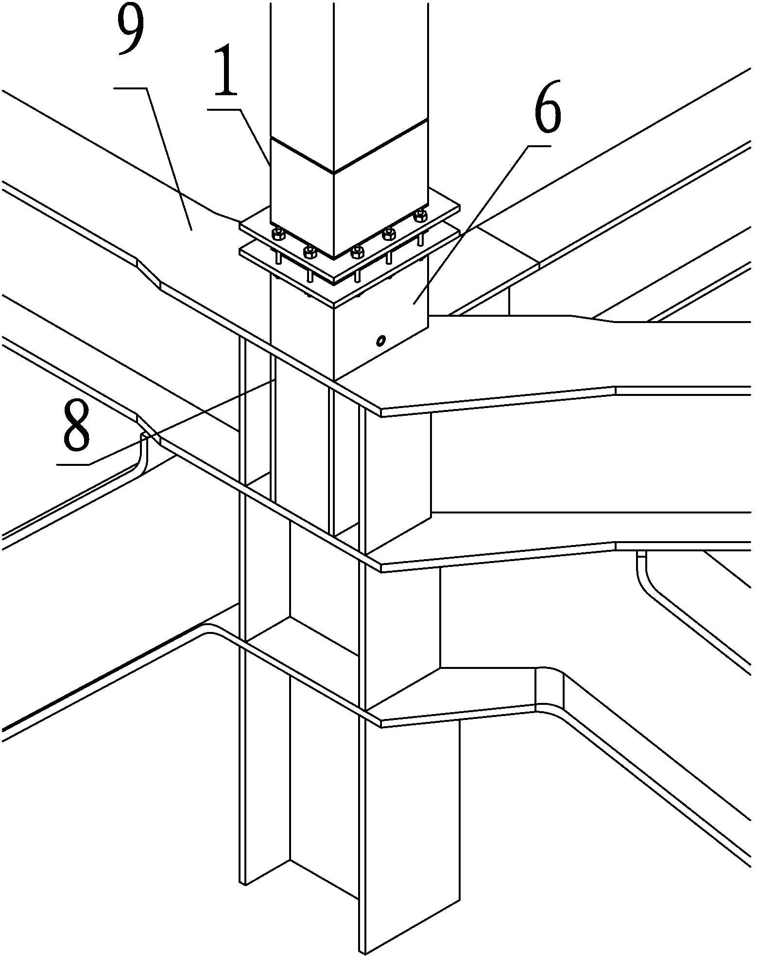
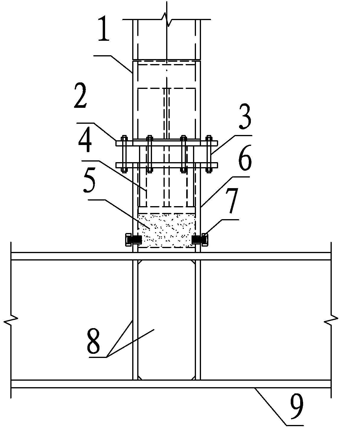
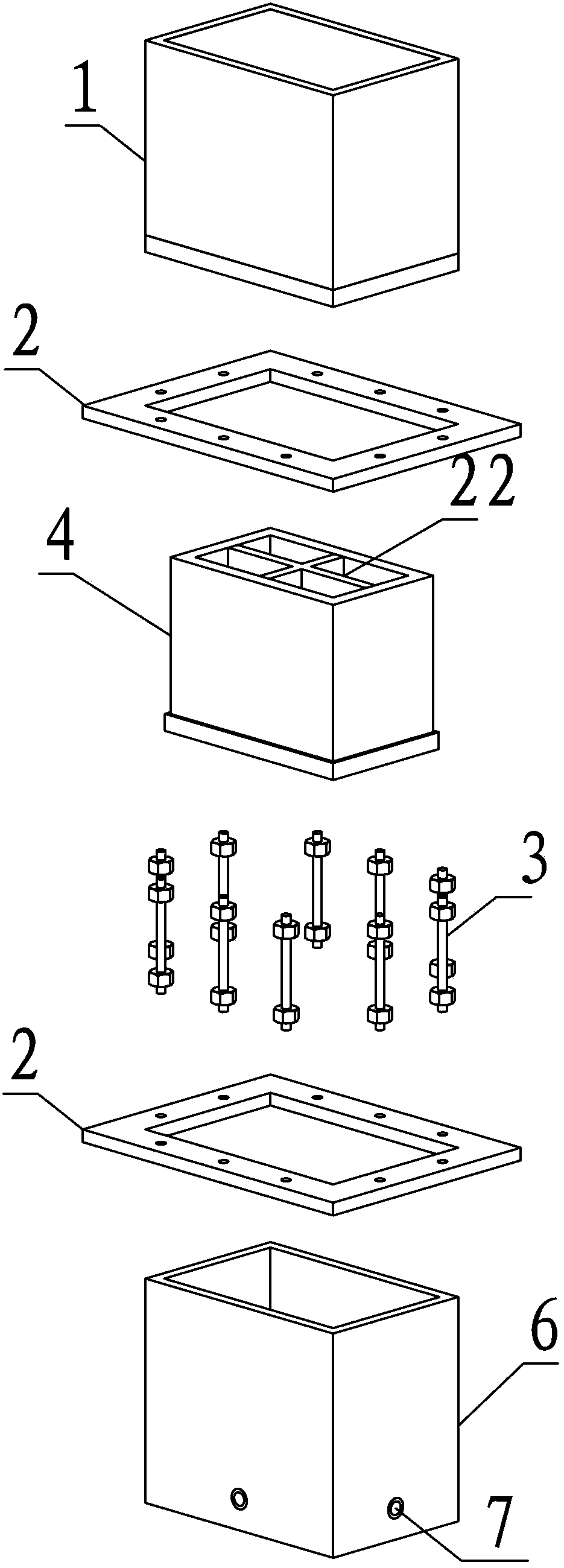
[0037] Such as Figure 1~Figure 6 , the parts mainly involved in the present invention are: hanging column 1, temporary connecting ring plate 2, temporary connecting rod 3, piston 4 at the bottom of the hanging column, high-strength steel sand 5, unloader 6, pressure relief valve 7, stiffening plate 8, Waist truss upper chord 9, cross stiffening plate at the bottom of the suspender 21, piston cross stiffening plate 22, piston bottom plate 23, flexible sealing material 31, pressure relief valve plugging steel bar 32, φ32 steel bar connector 41, threaded steel bar 42, nut 43 .

[0038] The overall building mentioned in this embodiment has a total construction area of ​​212,882 square meters. The tower has 62 floors above ground and 4 floors underground. The total height of the structure is 292.95 meters. The structure type of the tower i...


PUM


Abstract

The invention mainly discloses a method and equipment for sequentially constructing ultra-long hanging posts in a high-rise structure. The method includes steps of firstly, mounting a bottom uninstalling device of the hanging posts, filling high-strength steel sand in the uninstalling device and screwing down temporary connecting rods; secondly, mounting the hanging posts and steel frame beams adjacent to the hanging posts until a hanging post top structure is completely constructed; thirdly, synchronously unscrewing pressure release valves on the periphery of the uninstalling device to uninstalling the hanging posts; fourthly, cleaning residual steal sand in the uninstalling machine after the hanging posts are completely uninstalled, removing the temporary connecting rods, cutting off temporary connecting annular plates, sealing gaps between a bottom piston of the hanging posts and the uninstalling device and performing anti-corrosion treatment on the gaps between the bottom piston of the hanging posts and the uninstalling device so as to completely constructing the hanging posts. The equipment comprises the uninstalling device, the pressure release valves, the two temporary connecting annular plates, the multiple temporary connecting rods, the bottom piston of the hanging posts and the high-strength steel sand. The method and the equipment have the advantages that construction temporary measures can be reduced, the installation efficiency can be improved, the construction period can be shortened, the hanging posts can be conveniently and quickly uninstalled, and efficient and high-quality uninstalling work can be implemented.

Description

technical field [0001] The invention relates to the technical field of construction of steel structure suspenders, in particular to a sequential construction method and equipment for super-long suspenders in high-rise structures. Background technique [0002] With the development of modern building structures, the building space structure is becoming more and more complex. In order to meet the requirements of architects for large space and long span, steel structure hanging columns have been widely used. At the same time, because the steel structure davit is only subjected to tension, it can give full play to the mechanical properties of steel, so the davit structure is also favored by structural engineers. [0003] Although the steel structure davit has many advantages, it has caused many difficulties in construction due to its unique force-bearing form. In particular, there is no relatively mature construction method in China for the construction of super-long suspenders ...

Claims


Application Information

Patent Timeline
IPC IPC(8): E04G21/14E04G21/16
Inventor 郦宏伟赵海钢章伟松章立明俞奇效娄峰刘中华
Owner ZHEJIANG JINGGONG STEEL BUILDING GRP
Learn More