Oil way system for aerodynamic engine

An aerodynamic and oil circuit system technology, applied in the direction of engine lubrication, engine components, machines/engines, etc., can solve problems such as insufficient lubrication of parts and components

Active Publication Date: 2013-12-18
周登荣 +1
View PDF8 Cites 5 Cited by
  • Summary
  • Abstract
  • Description
  • Claims
  • Application Information

AI Technical Summary

Problems solved by technology

However, when the number of components in the engine increases, lubrication is required between t...

Method used


Image

  • Oil way system for aerodynamic engine

Examples


Embodiment Construction

[0028] The following description is merely exemplary in nature and not intended to limit the disclosure, application or use. The specific implementation of the oil circuit system of the aerodynamic engine of the present invention will be further described below in conjunction with the accompanying drawings.

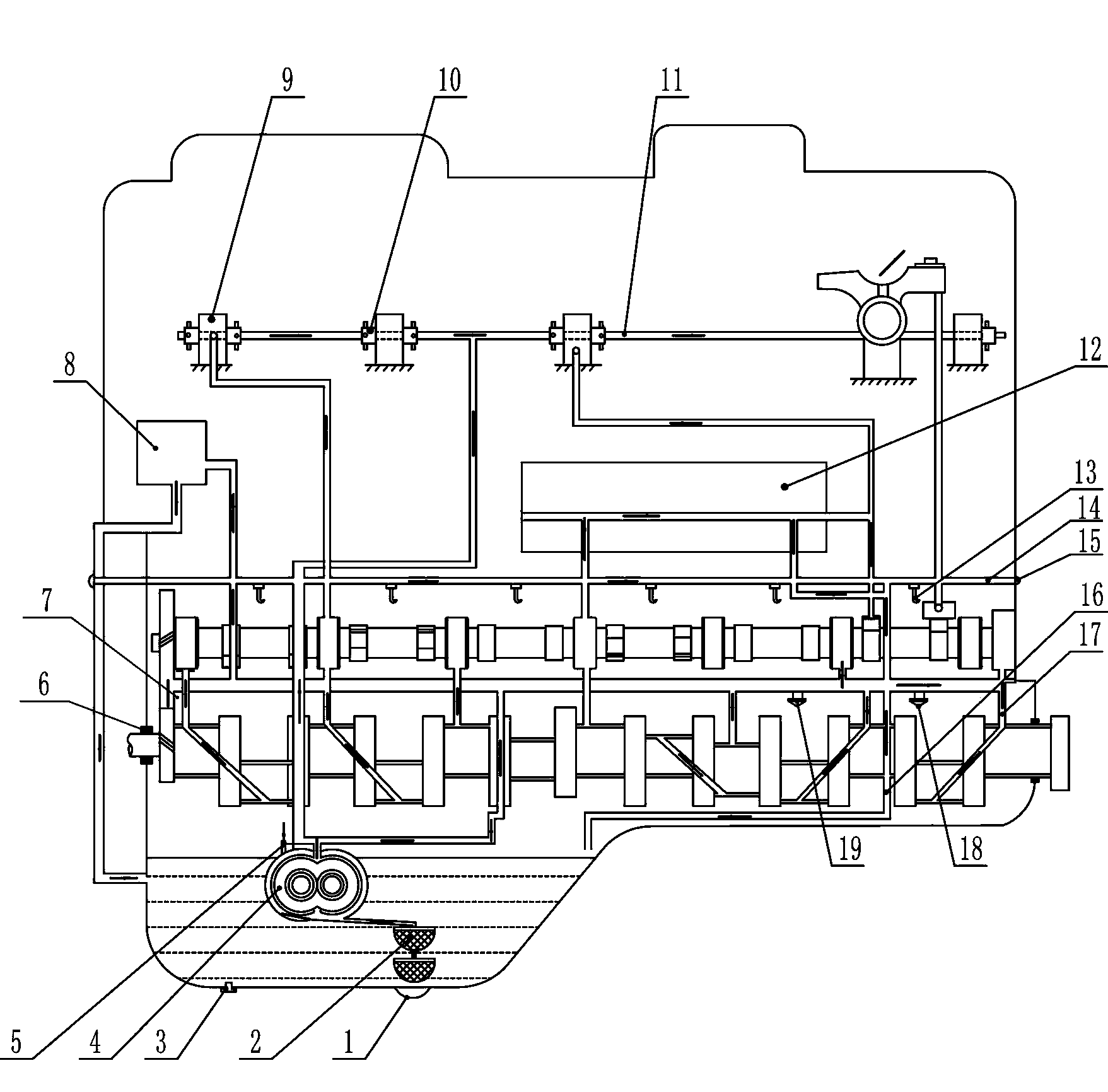
[0029] see figure 1 (The direction of the arrow is the direction of oil flow), which shows the structural schematic diagram of a preferred embodiment of the oil circuit system of the aerodynamic engine. The lubrication method of this engine adopts the parallel filter lubrication method, and the crankshaft shaft diameter, connecting rod shaft diameter, camshaft shaft diameter, camshaft thrust flange, timing gear, rocker arm shaft 11 and rocker arm 10 of the engine adopt pressure lubrication ; When the engine is working, the oil droplets or oil mist splashed by the moving parts are used to lubricate the piston, piston ring, piston pin, cylinder wall, valve, tappet and cam....


PUM


Abstract

The invention relates to a lubricating system for engines, particularly to an oil way system for an aerodynamic engine. The oil way system comprises pressure lubrication, splash lubrication, a pipeline, two magnet suction filters and two strainers which are stacked together, wherein the pressure lubrication is adopted on a crankshaft diameter of the engine, a connecting rod shaft diameter, a cam shaft diameter, a cam shaft thrust flange, a timing gear, a rocker arm shaft and the like; the splash lubrication is adopted on a piston, a piston ring, a piston pin, a cylinder wall, a valve, a tappet, a cam and the like; the pipeline is used for lubricating an air controller. According to the oil way system, only one pipeline is added to lubricate the controller, so that the inner space of the engine is saved.

Description

technical field [0001] The invention relates to the technical field of engines, in particular to an oil circuit system of an aerodynamic engine. Background technique [0002] During the use of the automobile engine, the colloid and dirt in the oil passage continue to increase, which will cause the cylinder pressure to drop, and the actual performance is insufficient power and high fuel consumption. The crankcase vents can also become clogged with the resulting dirt, causing the pressure inside the crankcase to rise, causing the oil to burn. If it is not cleaned in time, the dirt in the lubricating oil passage will accumulate more and more, resulting in the narrowing of the lubricating oil passage, the lubricating oil cannot fully reach the friction surface, and the engine will wear prematurely. Therefore, the lubricating oil passage system of the engine is very important . [0003] In addition, currently on the engine, a series of fully variable valve lift moving parts suc...

Claims


Application Information

Patent Timeline
IPC IPC(8): F01M1/10F01M9/10F01M1/02F01M1/06F01M11/03F01M1/16
Inventor 周登荣周剑
Owner 周登荣
Why Eureka
Try Eureka