Front squint SAR imaging method based on hypersonic aircraft at level flight section

A technology of hypersonic speed and imaging method, which is applied in the field of radar, can solve the problems of not considering the spatial variability of frequency modulation, poor imaging effect, highly complex algorithm, etc. Effect

Active Publication Date: 2013-12-18
XIDIAN UNIV
View PDF1 Cites 21 Cited by
  • Summary
  • Abstract
  • Description
  • Claims
  • Application Information

AI Technical Summary

Problems solved by technology

[0005] The first method, nonlinear frequency scaling algorithm, such as Guangcai Sun, Xiuwei Jiang, Mengdao Xing, Zhijun Qiao, Yirong Wu, Zheng Bao in the paper "Focus improvement of highly squinted data based on azimuth nonlinear scaling" (IEEE transaction on geoscience and remote sensing VOL49, O6, JUNE2011.) proposed an azimuth nonlinear frequency-variation standard ANCS algorithm. This algorithm considers the Doppler space-variation and range space-variation of the range modulation frequency, and can accurately detect large scenes with forward oblique angles of view. Imaging, but the algorithm is highly complex, the algorithm has a large amount of calculation, and it can only be used for non-real-time imaging. It is very unsuitable for hypersonic platforms with high real-time requirements
[0006] The second method is the decoupled EFSA algorithm, such as Liu Gaogao, Zhang Linrang, Liu Nan, Liu Xin, Zhang Bo, and Chen Guangfeng in the paper "Research on Imaging Algorithms for Hypersonic Vehicles" (Journal of Xidian University (Natural Science Edition) ) 2012, 39(5): 93-100) proposed a decoupled extended FM variable scale EFSA algorithm, which refers to the missile-borne FM continuous wave imaging model, and can be decoupled at a larg...

Method used


Image

  • Front squint SAR imaging method based on hypersonic aircraft at level flight section
  • Front squint SAR imaging method based on hypersonic aircraft at level flight section
  • Front squint SAR imaging method based on hypersonic aircraft at level flight section

Examples


Embodiment Construction

[0036] The present invention will be further described below in conjunction with the accompanying drawings.

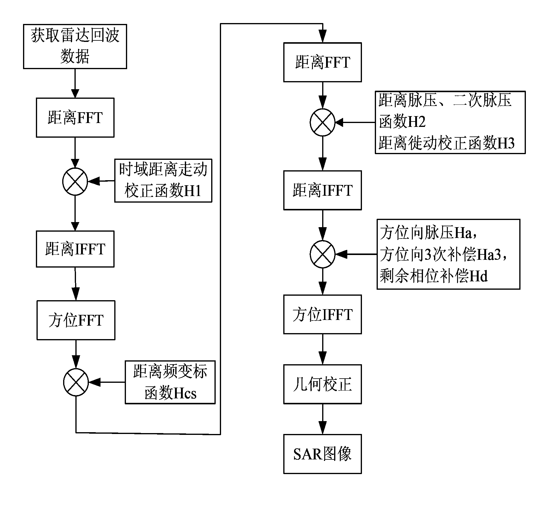
[0037] refer to figure 1, the specific implementation steps of the present invention are as follows:

[0038] Step 1. Obtain radar echo data.

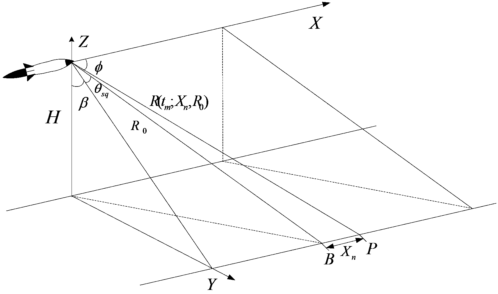
[0039] 1a) The synthetic aperture radar device is at the front end of the hypersonic vehicle, and the hypersonic vehicle follows the figure 2 The geometric relationship shown is to fly along the X-axis direction at the speed v, the X-axis direction is the azimuth direction, the Y-axis direction is the distance direction, and the radar beam is at a fixed forward oblique angle of view θ sq When the ground scene is irradiated, the instantaneous slant distance between the radar and the center of the scene is R(t m ;X n , R 0 ):

[0040] R ( t m ; X n , R ...


PUM


Abstract

The invention discloses a front squint SAR imaging method based on a hypersonic aircraft at the level flight section. The front squint SAR imaging method mainly solves the problem that orientation pulses are compressed to distort on the condition of a small front squint angle of a high-speed platform. The front squint SAR imaging method includes the first step of obtaining radar echo signals, the second step of carrying out time domain calibration distance walking processing on the radar echo signals, the third step of carrying out distance linear frequency scaling processing after the time domain calibration distance walking processing, and obtaining two-dimensional frequency domain signals, the fourth step of carrying out range pulse compression and secondary pulse compression processing on the two-dimensional frequency domain signals, the fifth step of carrying out azimuth pulse compression and space-variant compensation processing on range processing results, and the sixth step of carrying out geometric distortion correction on azimuth processing results to obtain front squint SAR images. The front squint SAR imaging method reduces imaging complexity, and realizes high-precision front squint SAR imaging on the condition of the hypersonic platform; obtained geometric distortion correction images are favorable for follow-up SAR image processing and application and can be used for ground target recognition, scene matching and the like.

Description

technical field [0001] The invention belongs to the technical field of radar, and relates to a synthetic aperture radar (SAR) imaging method, which can be used for two-dimensional imaging of ground scenes by forward squint SAR in the level flight section of a hypersonic vehicle. Background technique [0002] Hypersonic vehicles have become a research hotspot in various countries in recent years. The United States, Russia, France, Germany, Japan, India and other countries are all conducting research in this area. Hypersonic aircraft can fly at Mach 5-10, and can achieve global strikes in two hours, which has extremely high application potential. The radar imaging of the hypersonic vehicle carrier has extremely high research value, and the forward-squinting SAR imaging is an important mode of hypersonic vehicle imaging. [0003] Due to the high flight speed and forward squint imaging of the hypersonic vehicle, the SAR echo signal will have a very large range migration, and th...

Claims


Application Information

Patent Timeline
IPC IPC(8): G01S13/90
Inventor 刘峥王震谢荣杨树慧
Owner XIDIAN UNIV
Why Eureka
Try Eureka