Catalytic converter assembly welding method for vehicle exhaust system

An assembly welding method and an automobile exhaust system technology, applied in welding equipment, welding equipment, auxiliary welding equipment, etc., can solve problems such as uncontrollable deformation, difficult product quality assurance, and complicated operation

Active Publication Date: 2013-12-25
保定市屹马汽车配件制造有限公司
View PDF6 Cites 30 Cited by
  • Summary
  • Abstract
  • Description
  • Claims
  • Application Information

AI Technical Summary

Problems solved by technology

This method causes free deformation of the workpiece when the product is heated during the welding process, the amount of deformation cannot be controlled, and the product quality is difficult to guarantee
In order to control the amount of deformation, the welding method has been improved to reduce the spot welding process of the assembly, the assembly welding jig is designed, and the product is assembled as a whole before welding. This integrated welding process is conducive to controlling the change of the assembly angle. The quality has been greatly improved; but the

Method used


Image

  • Catalytic converter assembly welding method for vehicle exhaust system
  • Catalytic converter assembly welding method for vehicle exhaust system
  • Catalytic converter assembly welding method for vehicle exhaust system

Examples


Embodiment Construction

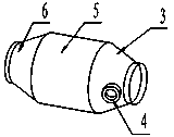
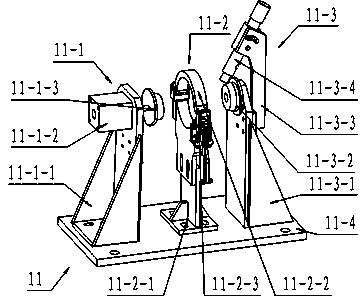
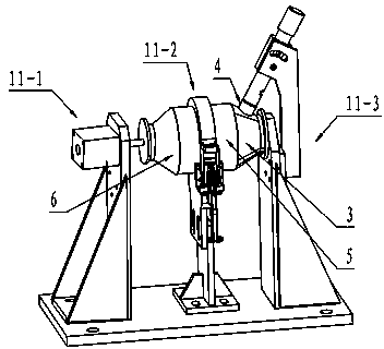
[0025] see Figure 7 , the catalytic converter assembly consists of a front flange 1, a front connecting pipe 2, a front cone 3, a carrier shell 5, a rear cone 6, a middle connecting pipe 7, a soft connection 8, a rear connecting pipe 9, and a rear flange 10. The parts are welded into one body through eight welds, and the oxygen sensing nut 4 is arranged on the front cone. The shape of the catalytic converter assembly is irregular, and it also includes soft connections. It is difficult to position during the welding process. It is difficult to ensure the size and position of the product. It is difficult to control the shrinkage of the welded parts. In addition, the heat of the pipe body will cause serious deformation of the assembly. , resulting in poor consistency of the workpiece after welding, making it difficult to meet the requirements for the assembly position accuracy of the catalytic converter assembly. For a long time, no matter the method of spot welding each componen...


PUM


Abstract

A catalytic converter assembly welding method for a vehicle exhaust system uses incremental part welding and includes the following steps of welding a front cone, a carrier shell and a rear cone on carrier shell subassembly welding equipment to form carrier shell subassembly, welding a front flange, a front connection tube, a middle connection tube, and the welded carrier shell subassembly on a front subassembly welding equipment to form a front subassembly, and welding flexible connection, a rear connection tube, a rear flange and the front subassembly on assembly welding equipment so as to form a catalytic converter assembly. The catalytic converter assembly welding method for the vehicle exhaust system has the advantages of greatly reducing cumulative welding residual stress caused by integrated welding and forming, avoiding deformation of complex welding on junctions of various part, improving product quality, eliminating quality problems caused by welding residual stress and a large of unqualified products owing to the welding deformation, and improving production efficiency.

Description

technical field [0001] The invention relates to a welding technology, in particular to a welding method for a catalytic converter assembly used in an automobile exhaust system. Background technique [0002] The catalytic converter assembly for automobile exhaust system is an important part of the automobile exhaust system, which undertakes the tasks of automobile exhaust emission and noise attenuation. In recent years, with the improvement of the driving performance requirements of the whole vehicle, the automobile manufacturing industry has gradually strengthened the improvement of engine performance and exhaust emission. The catalytic converter assembly is composed of multiple parts through welding. A traditional welding method is to assemble the parts of the catalytic converter assembly with simple tooling first, and then use arc welding equipment to fix the parts assembly by spot welding. , and then weld each ring. This method causes free deformation of the workpiece w...

Claims


Application Information

Patent Timeline
IPC IPC(8): B23K31/02B23K37/053
Inventor 刘小平
Owner 保定市屹马汽车配件制造有限公司
Why Eureka
Try Eureka