Fast and accurate positioning device and method for railway transit vehicles

A rail transit vehicle and precise positioning technology, which is applied to the rapid and precise positioning device and positioning field of rail transit vehicles, can solve the problems of long time required, inaccurate positioning, and inability to locate, and achieve short positioning time and sampling frequency The effect of high and low sampling frequency

Active Publication Date: 2013-12-25
BEIJING JIAOTONG UNIV +1
View PDF4 Cites 30 Cited by
  • Summary
  • Abstract
  • Description
  • Claims
  • Application Information

AI Technical Summary

Problems solved by technology

However, there are two problems. The first is that in order to meet the requirements of precise positioning, the sampling frequency of the selected laser displacement sensor is very high, followed by a large amount of data, and it takes a long time to perform positioning calculations; The second is that the above method depends to a certain extent on the specific track characteristics of the turnout. When there is no turnout on the line or the test section does not pass through the turnout, the positioning will be inaccurate or even impossible.

Method used


Image

  • Fast and accurate positioning device and method for railway transit vehicles
  • Fast and accurate positioning device and method for railway transit vehicles
  • Fast and accurate positioning device and method for railway transit vehicles

Examples


Embodiment 1

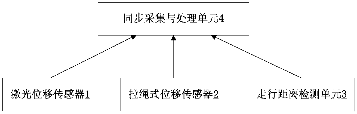
[0042] refer to figure 1 , figure 1 It is a structural schematic diagram of an embodiment of the rapid and precise positioning device for rail transit vehicles of the present invention, including: a laser displacement sensor 1, a drawstring displacement sensor 2, a rail vehicle travel distance detection unit 3 and a synchronous acquisition and data processing unit 4.

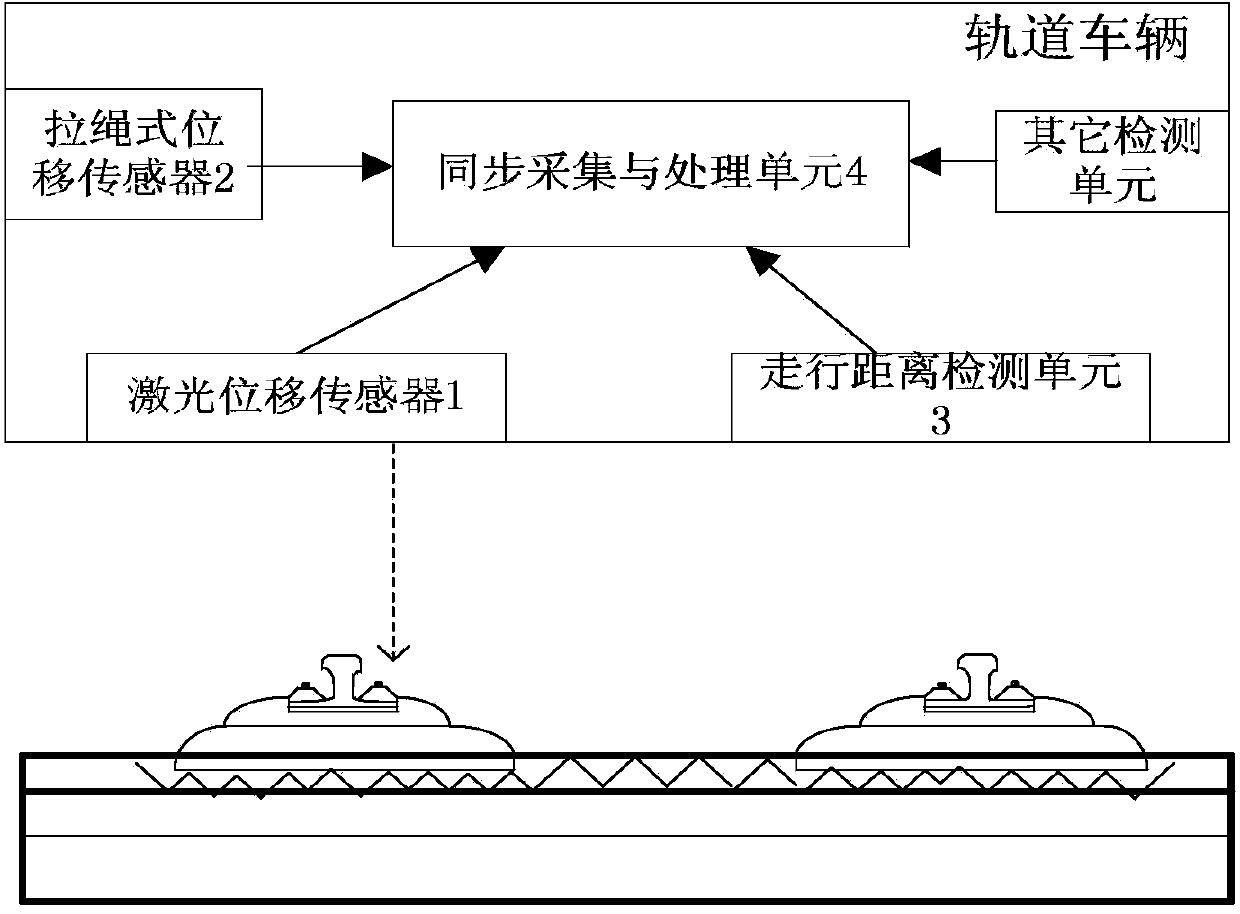
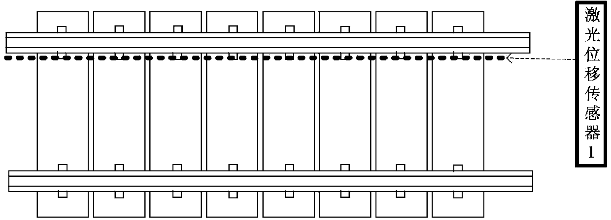
[0043] Among them, refer to figure 2 and image 3 As shown, the laser displacement sensor 1 is aligned near the inner fastener of the track, and the output of the laser displacement sensor 1 is the distance between the installation position and the surface of the track.

[0044] refer to Figure 4 , two pull-rope displacement sensors 2 are horizontally installed between the car body 5 and the bogie 6 of the rail vehicle, and are used to detect the horizontal distance between the car body 5 and the bogie 6, and the distance between the car body 5 and the bogie 6 The change in the horizontal distance of is us...

Embodiment 2

[0058] refer to Figure 7 , this embodiment is a system for detecting deformation of a tunnel body using the vehicle-mounted positioning device described in the present invention. This system includes a laser displacement sensor, a drawstring displacement sensor, a wheel shaft pulse sensor, a data synchronous acquisition circuit, a data processing module and a data processing software. It also includes some other detection equipment, such as other sensors, including GPS receivers, tunnel section measurement sensors and vehicle body attitude measurement sensors. The system is mounted on a rail vehicle or a manually propelled rail trolley. During the detection process, the data synchronous acquisition circuit synchronously acquires the output of each sensor, and then transmits it to the data processing module for real-time storage. The judgment of tunnel body deformation can be performed in real time or offline. (1) First, the data processing module aligns the data collected ...


PUM


Abstract

The invention discloses a fast and accurate positioning device and method for railway transit vehicles. The positioning device comprises a laser displacement sensor, a cord-pull-type displacement sensor, a railway vehicle travelling distance detecting unit and a synchronous collecting and data processing unit. The vehicular laser displacement sensor is used to detect the distance between a vehicle and railway, the cord-pull-type displacement sensor is used to detect yaw angle of the vehicle travelling along the direction of the railway, vehicle travelling distance is obtained by the aid of a wheel axle pulse sensor, and vehicle yaw angle data and railway feature data are obtained by using the vehicular data collecting and processing module for calculation. The obtained vehicle yaw angle data and the railway feature data are matched to roughly position the vehicle, position correction is performed on the obtained railway feature data according to the rough positioning result, and the corrected railway feature data is matched with historical railway feature data to realize high-precision absolute or relative positioning.

Description

technical field [0001] The invention relates to train operation control and infrastructure dynamic detection of rail traffic, in particular to a fast and precise positioning device and positioning method for rail traffic vehicles. Background technique [0002] Train positioning technology is one of the key technologies of rail transit train operation control, and it is the basis for ensuring driving safety and shortening the running interval between trains. The existing train positioning technology mainly uses the odometer based on wheel axle counting, together with other auxiliary means, such as query transponder, Doppler radar, track circuit, inter-track induction loop, wireless spread spectrum positioning, satellite positioning system, line map Matching, line image matching, turnout position matching, catenary limiter position matching and other technologies can automatically correct the cumulative error of the odometer caused by factors such as wheel idling, slipping, se...

Claims


Application Information

Patent Timeline
Patent Type & Authority Applications(China)
IPC IPC(8): B61L25/02
Inventor 朱力强刘光武何霖余祖俊张志良袁敏正张玉梅杨玲芝徐顺明
Owner BEIJING JIAOTONG UNIV
Why Eureka
Try Eureka