Space microgravity environment ground simulation experiment device

A technology of ground simulation and experimental equipment, applied in the field of simulation, can solve the problems of high cost and short test time, and achieve the effect of low cost, convenient operation and unlimited test time

Active Publication Date: 2013-12-25
HARBIN INST OF TECH
View PDF3 Cites 64 Cited by
  • Summary
  • Abstract
  • Description
  • Claims
  • Application Information

AI Technical Summary

Problems solved by technology

This solution is susceptible to water resistance and turbulence, is very costly and requires a very good seal during the test
The free fall method is to make the test target

Method used


Image

  • Space microgravity environment ground simulation experiment device
  • Space microgravity environment ground simulation experiment device
  • Space microgravity environment ground simulation experiment device

Examples


Embodiment 1

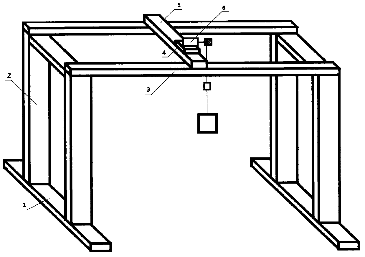
[0014] Such as figure 1 As shown, a space microgravity environment ground simulation experiment device includes a foundation 1, two supporting columns 2, a horizontal air-floating rail 3, a longitudinal air-floating rail 5, a pulley 4 and a weightlessness simulation control system 6, and two supporting columns 2 They are respectively installed horizontally on the foundation 4, the horizontal air-floating guide rail 3 is installed on the two supporting columns 2, the longitudinal air-floating guide rail 5 is installed on the horizontal air-floating guide rail 3, the trolley 4 is installed on the longitudinal air-floating guide rail 5, and the weightlessness simulation control System 6 is installed on the tackle 4, and controller is installed on the tackle 4; Described weightlessness simulation control system 6 comprises servomotor 7, coiling wheel 8, hanging wire 9, force sensor 10 and aircraft 11, and servomotor 7 connects coil Wire wheel 8, wire winding wheel 8 are connected ...

Embodiment 2

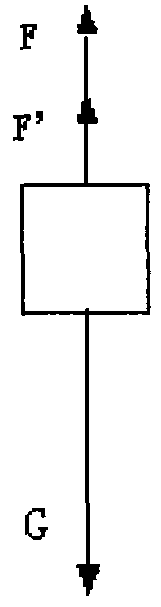
[0016] according to figure 1 , figure 2 , the working principle of the present invention is such: at first assume that aircraft is subjected to the effect of a force passing through the center of mass of the aircraft in three-dimensional space. Force can be equivalently decomposed into horizontal component and vertical component in three-dimensional space. The horizontal component of the force pulls the trolley to move in the horizontal direction, because there is approximately no friction between the air-floating guide rail and the trolley, so the approximately friction-free movement of the aircraft in the horizontal direction is realized by means of the air-floating guide rail; the vertical force of the force The component changes the feedback value of the force sensor that senses the pulling force of the hanging wire, thereby controlling the drive motor to make a corresponding response according to a predetermined control rule to ensure that the tension of the hanging wir...

Embodiment 3

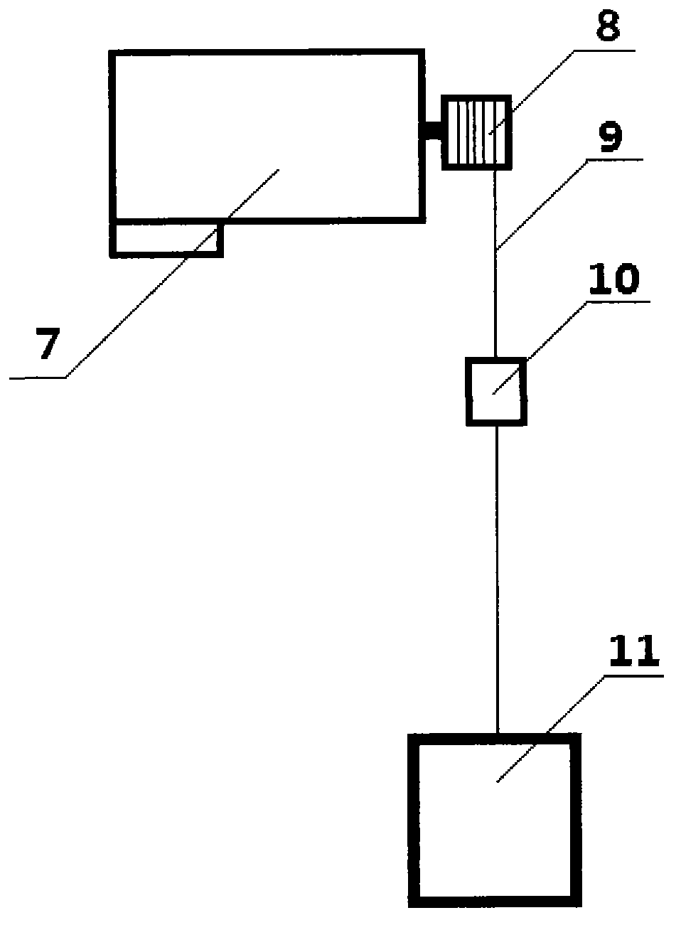
[0018] to combine figure 2 , image 3 , the structural design of the weightlessness simulation control system can be as follows figure 2 As shown, the weightlessness simulation control system 6 is composed of a motor 7 , a winding wheel 8 , a hanging wire 9 , and a force sensor 10 . The motor 7 is connected to the wire winding wheel 8 , the wire winding wheel 8 is connected to the hanging wire 9 , the hanging wire 9 is connected to the force sensor 10 , and the sensor 10 is connected to the aircraft 11 .

[0019] The working process of the weightlessness simulation control system is as follows: the control command of the servo motor comes from the controller placed on the pulley. When the tension of the hanging wire changes, the feedback value of the force sensor that senses the pulling force of the hanging wire changes, and the controller calculates the control command through the feedback value of the force sensor. The input signal of the controller is the feedback value...


PUM


Abstract

The invention relates to a space microgravity environment ground simulation experiment device. The device comprises a foundation, two support posts, a transverse air floating guide rail, a longitudinal air floating guide rail, a slide trolley and a weightless simulation control system. Two support posts are respectively mounted on the foundation horizontally, the transverse air floating guide rail is mounted on the two support posts, the longitudinal air floating guide rail is mounted on the transverse air floating guide rail, the slide trolley is mounted on the longitudinal air floating guide rail, weightless simulation control system is mounted on the slide trolley, and a controller is mounted on the slide trolley. The weightless simulation control system comprises a servo motor, a coiling wheel, a hang spring, a force sensor and an aircraft, the servo motor is connected with the coiling wheel, the coiling wheel is connected with the hang spring, the hang spring is connected with the force sensor, the force sensor is connected with the aircraft, and the controller is respectively connected with the force sensor and the servo motor in an electrical signal manner. The device is simple in structure, high in vividness, convenient to operate, easy to achieve, low in cost, and unlimited in experiment time.

Description

technical field [0001] The invention relates to a simulation technology, in particular to a simulation experiment device for a space microgravity environment. Background technique [0002] The spacecraft is in a state of weightlessness when it is running in space. In order to ensure the success of the spacecraft’s on-orbit mission, it is necessary to conduct sufficient experimental analysis and verification on the ground. Therefore, it is important to build an experimental system that can simulate the space microgravity environment under the 1g environment on the ground. Value and application context. [0003] According to literature search, China Invention Patent No.: 200910072287.8, the patent name is: three-dimensional microgravity smart air foot, which proposes a device for simulating complex space microgravity environment combined with mechanical / electrical / pneumatic, but its structure is complicated, and it cannot be used in practical applications. Difficult to achiev...

Claims


Application Information

Patent Timeline
IPC IPC(8): B64G7/00
Inventor 夏红伟王有松马广程王常虹宋效正
Owner HARBIN INST OF TECH
Why Eureka
Try Eureka