Hydraulic rotary braking energy-saving control system

An energy-saving control system and slewing brake technology are applied in the direction of fluid pressure actuators, servo motors, servo motor components, etc., which can solve the problems of system heating, excavator machine life reduction, energy loss, etc., to improve work efficiency, Improve movement coordination, good energy saving effect

Active Publication Date: 2013-12-25
NANJING UNIV OF TECH +1
View PDF8 Cites 18 Cited by
  • Summary
  • Abstract
  • Description
  • Claims
  • Application Information

AI Technical Summary

Problems solved by technology

The deceleration and braking torque of the slewing mechanism of the excavator is large and the frequent slewing action will inevitably cause a large amount of energy loss. At the same time, it will also cause system heating, cavitation and other defects in the hydraulic system, which will directly lead to the reduction of the service life of the excavator.

Method used


Image

  • Hydraulic rotary braking energy-saving control system
  • Hydraulic rotary braking energy-saving control system
  • Hydraulic rotary braking energy-saving control system

Examples


Embodiment

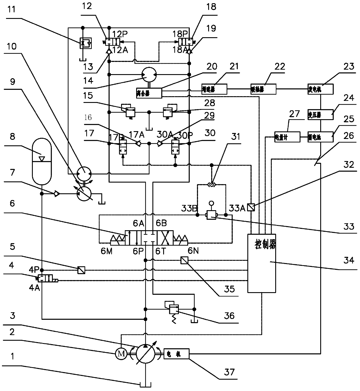
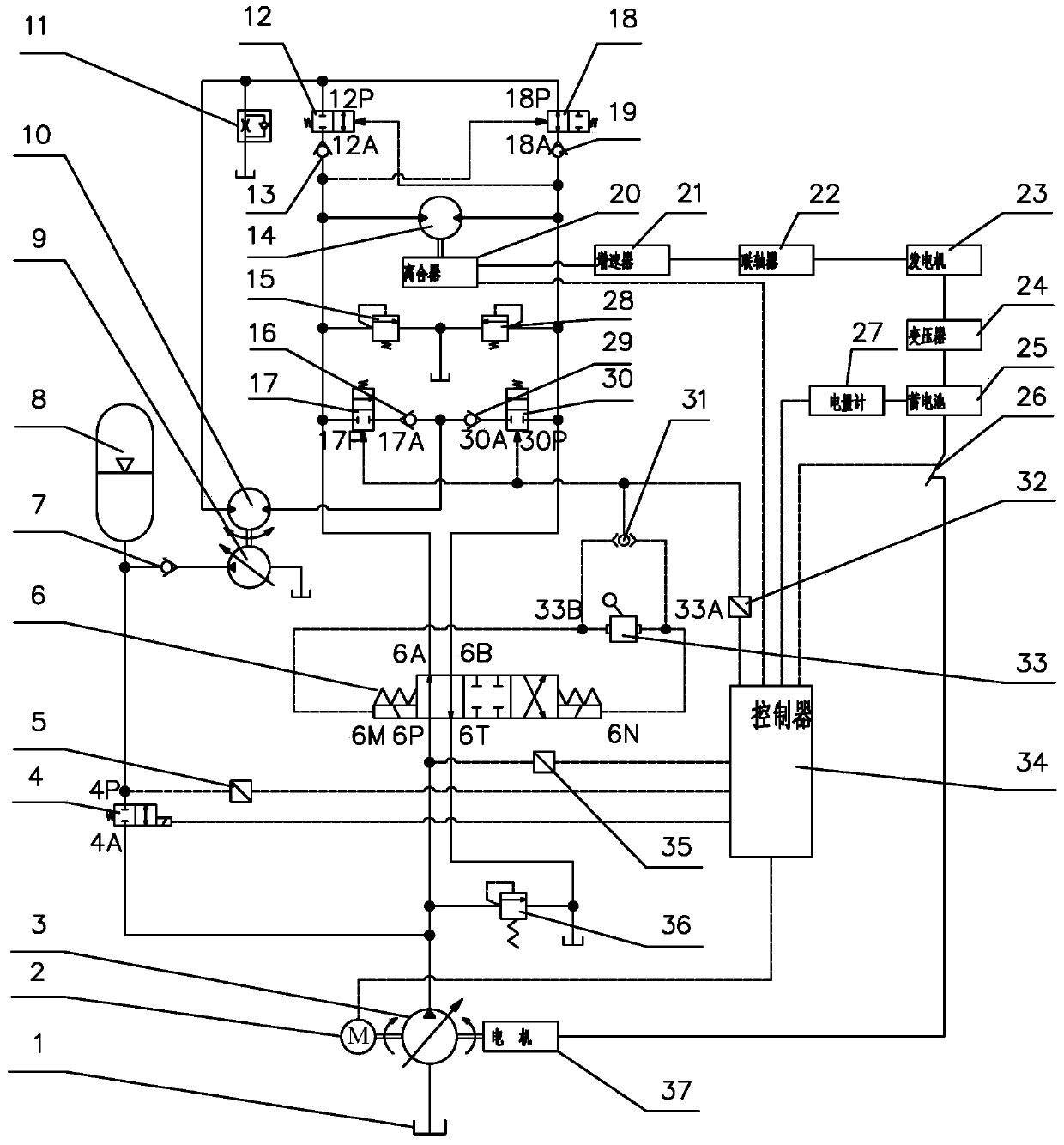
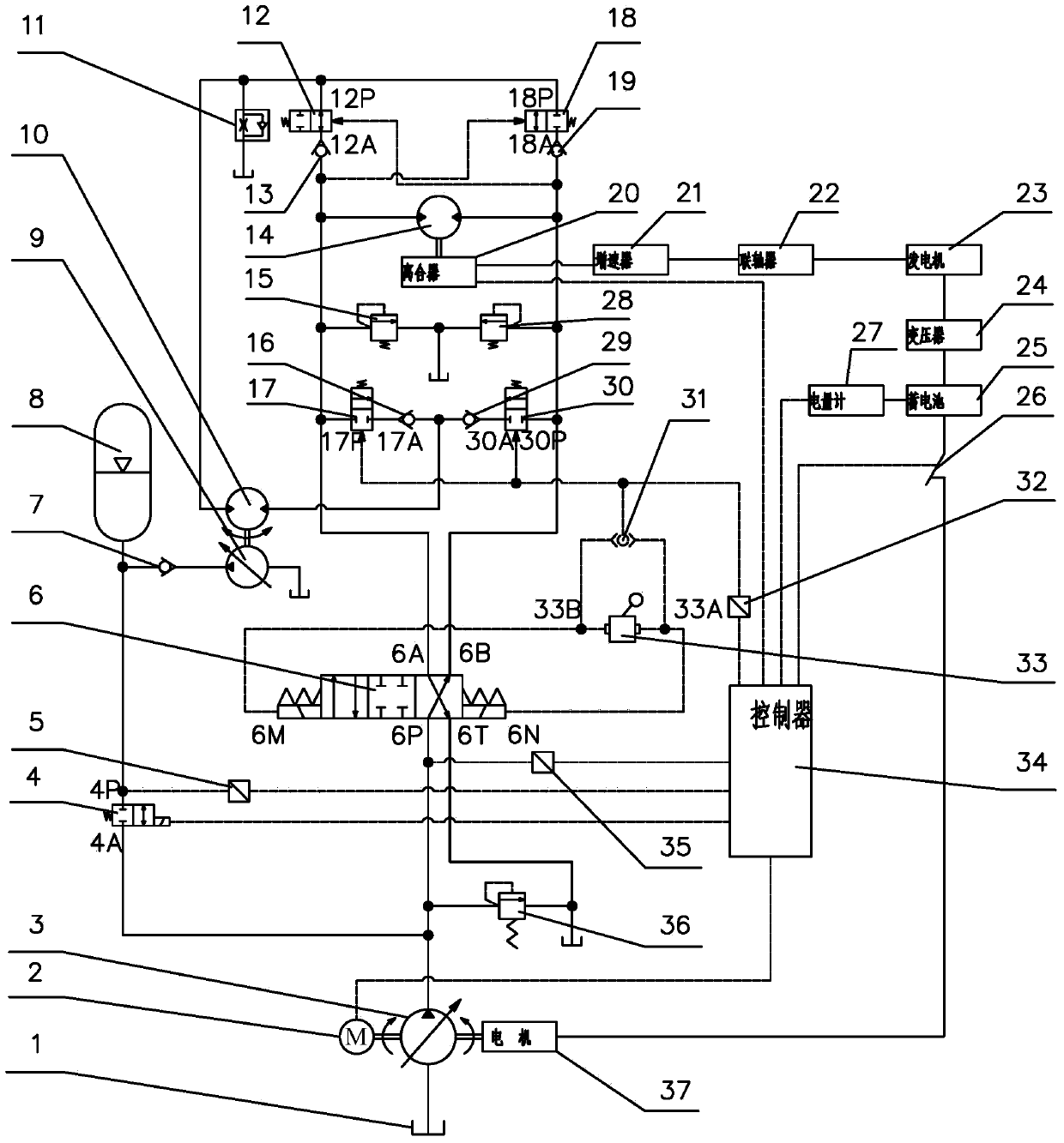
[0031] Such as figure 1As shown, the outlet of the first variable pump 3 is connected with the oil inlet 6P of the three-position four-way reversing valve 6, and the first pilot oil port 6M of the three-position four-way reversing valve 6 is connected with the second port of the pilot oil circuit control handle. The outlet 33B is connected, and the second pilot oil port 6N of the three-position four-way reversing valve 6 is connected with the first outlet 33A of the pilot oil circuit control handle; the first oil outlet 6A of the three-position four-way reversing valve 6 is connected with the third The inlet 17P of the hydraulically controlled reversing valve 17, the inlet of the first relief valve 15, the inlet of the rotary motor 14, the pilot oil port of the second hydraulically controlled reversing valve 18, and the outlet of the second one-way valve 13 are connected; three positions The second oil outlet 6B of the four-way reversing valve 6 is connected with the inlet 30P...


PUM


Abstract

The invention discloses a hydraulic rotary braking energy-saving control system. The hydraulic rotary braking energy-saving control system comprises an oil tank, an engine, a first variable pump, an electromagnetic directional control valve, a three-position four-way directional control valve, a first one-way valve, an energy accumulator, a second variable pump, a first motor, a first pilot operated directional control valve, a second one-way valve, a rotary motor, a second overflow valve, a fourth one-way valve, a second pilot operated directional control valve, a third pilot operated directional control valve, a third one-way valve, a clutch, a speed increasing gear, a coupler, a generator, a transformer, a storage battery, a motor-operated switch, a third overflow valve, a fifth one-way valve, a fourth pilot operated directional control valve, a controller, a first overflow valve and a motor. On the basis of an energy recycling device, a novel energy storage mode is added for the hydraulic rotary braking energy-saving control system, so that energy of high braking torque generated during rotary braking every time is converted, and is stored in the storage battery in the form of electric energy, and the energy recycling efficiency in the rotary braking process can be high.

Description

technical field [0001] The invention relates to an energy-saving control system for engineering machinery, in particular to a hydraulic slewing brake energy-saving control system for a hydraulic excavator with a hydraulic slewing system. Background technique [0002] As one of the important equipment of construction machinery, hydraulic excavator has harsh working environment, high energy consumption, and serious exhaust emissions. Research on energy saving and emission reduction is the focus and difficulty in this field. The deceleration and braking torque of the slewing mechanism of the excavator is large and the frequent slewing action will inevitably cause a large amount of energy loss. At the same time, it will also cause system heating, cavitation and other defects in the hydraulic system, which will directly lead to the reduction of the service life of the excavator. [0003] In a standard working cycle of the excavator, there are two slewing movements. According to ...

Claims


Application Information

Patent Timeline
Patent Type & Authority Applications(China)
IPC IPC(8): F15B11/17F15B1/04F15B13/02
CPCY02E60/16
Inventor 殷晨波姜雪峰俞宏福曹东辉袁祖强
Owner NANJING UNIV OF TECH
Why Eureka
Try Eureka