rc oscillator

An oscillator and channel technology, which is used in pulse generation, electrical components, and electrical pulse generation. It can solve the problem of poor clock temperature coefficient, poor resistance to temperature changes of RC oscillators, and is not suitable for new portable mobile battery equipment. Environmental and other issues, to achieve the effect of low temperature drift

Active Publication Date: 2016-04-13
ZHUHAI ZHONGHUI MICROELECTRONICS
View PDF3 Cites 0 Cited by
  • Summary
  • Abstract
  • Description
  • Claims
  • Application Information

AI Technical Summary

Problems solved by technology

[0008] The RC oscillator with the above structure, although the reference circuit module 1 using the bandgap reference voltage source Bandgap can generate a reference voltage that does not change with temperature, but due to the influence of the temperature coefficient of resistance, the RC oscillator with this structure has no ability to resist temperature changes. Well, the tempco of the clock gets worse when using monotonic tempco type resistors
In addition, the structure of the RC oscillator is relatively complicated, and its minimum operating voltage V DDmin =V ref +V dsatn +|V dsatp |+|V thp |, It is difficult to work under the working power supply of 2v and below, and it is not suitable for the working environment powered by new portable mobile battery equipment

Method used


Image

  • rc oscillator
  • rc oscillator
  • rc oscillator

Examples


Embodiment Construction

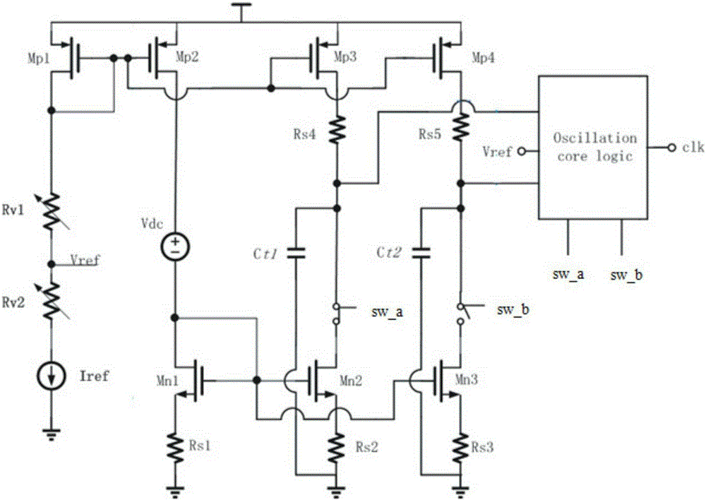
[0029] Such as image 3 As shown, the RC oscillator includes: an operating voltage V, a reference circuit module 10, a first P-channel MOS transistor Mp1, a second P-channel MOS transistor Mp2, a third P-channel MOS transistor Mp3, and a fourth P-channel MOS transistor. Tube Mp4, compensation resistor Rs4, compensation resistor Rs5, voltage drop module Vdc, first N-channel MOS transistor Mn1, second N-channel MOS transistor Mn2, third N-channel MOS transistor Mn3, resistor Rs1, degradation resistor Rs2, The degeneration resistor Rs3, the oscillating core logic circuit 30, the first timing capacitor Ct1, the second timing capacitor Ct2, the first discharge switch sw_a, and the second discharge switch sw_b.

[0030] In this embodiment, the compensating resistor Rs4 and the compensating resistor Rs5 are the same element, the degeneration resistor Rs2 and the degeneration resistor Rs3 are the same element, and the second N-channel MOS transistor Mn2 and the third N-channel MOS tra...


PUM


Abstract

The invention relates to an RC (resistor-capacitor) oscillator which comprises a working voltage, a reference circuit module, a first P-channel MOS (metal oxide semiconductor) tube, a third P-channel MOS tube, a fourth P-channel MOS tube, an oscillation core logic circuit, a first discharge switch, a second discharge switch, a first time sequence capacitor and a second time sequence capacitor. The RC oscillator is characterized in that a second end of the first discharge switch and a second end of the second discharge switch are respectively provided with a source degeneration current source composed of an N-channel MOS tube and a degeneration resistor. Based on the characteristic that output impedance of the source degeneration current source changes with temperature and current, the residual charge quantity on the time sequence capacitors can counteract the change of clock frequency caused by change of temperature and voltage of a working power supply, thereby realizing the RC oscillator having low temperature drift.

Description

【Technical field】 [0001] The invention belongs to the technical field of integrated circuit design, and in particular relates to an RC oscillator. 【Background technique】 [0002] In general, the RC oscillator generates an oscillating clock signal by delaying the charging and discharging of the capacitor. The frequency of the clock signal generated by this circuit structure is easily affected by factors such as the chip power supply voltage and the surrounding working environment temperature. In order to overcome the influence of the operating power supply voltage and ambient temperature on the output clock frequency of the RC oscillator, many designs and inventions have proposed various high-precision RC oscillators. figure 1 It is a classic RC oscillator, which includes: reference circuit module 1, P-channel MOS transistor Mp1S, P-channel MOS transistor Mp2S, P-channel MOS transistor Mp3S, oscillation core logic circuit 3, first timing capacitor Ct1S, second The timing cap...

Claims


Application Information

Patent Timeline
Patent Type & Authority Patents(China)
IPC IPC(8): H03K3/011
Inventor 王建军朱家训朱定飞邓廷梅月谭岳德向铭
Owner ZHUHAI ZHONGHUI MICROELECTRONICS
Why Eureka
Try Eureka