Light receiver

a light receiver and receiver technology, applied in the field of light receivers, can solve the problems of large size of light receivers, inability to meet the demands of today's precision, and complex light receivers according to de 19540590 a1

Active Publication Date: 2018-11-22
LEICA GEOSYSTEMS AG
View PDF0 Cites 0 Cited by
  • Summary
  • Abstract
  • Description
  • Claims
  • Application Information

AI Technical Summary

Benefits of technology

[0009]It is therefore an object of some embodiments of the present invention to provide an improved ...

Problems solved by technology

However, the light receiver according to DE 19540590 A1 is quite complex and does not satisfy nowaday's precision demands.
As a further disadvantage, the size of the light receiver is constrained as the larger the height of the N-shaped device, the longer the line-shaped receiving elements, the higher the electrical noise and the manufac...

Method used


Image

  • Light receiver
  • Light receiver
  • Light receiver

Examples


Embodiment Construction

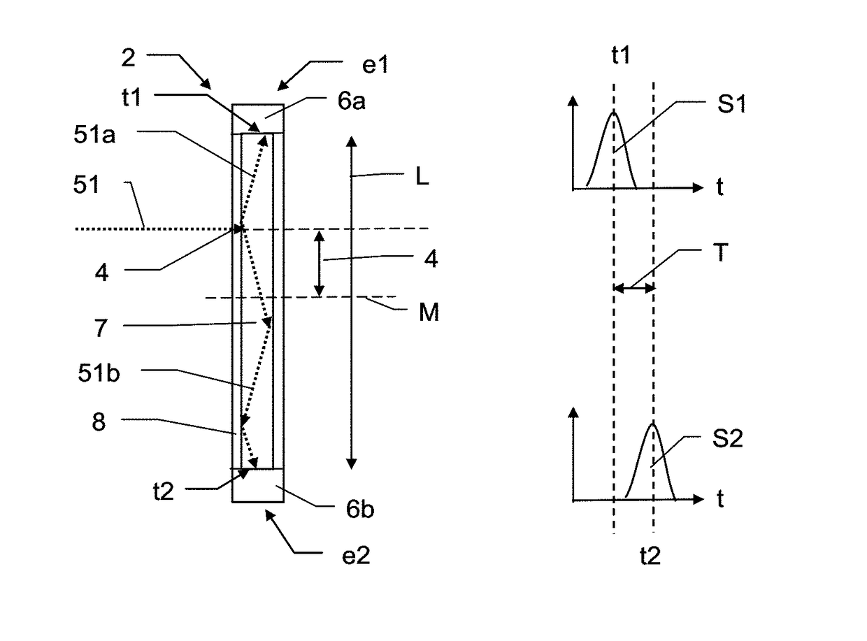
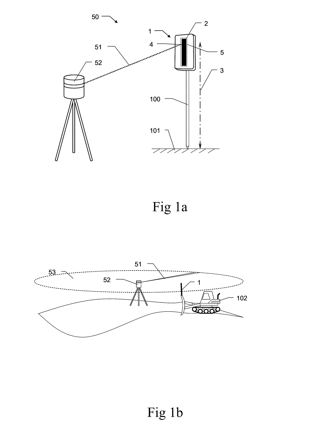
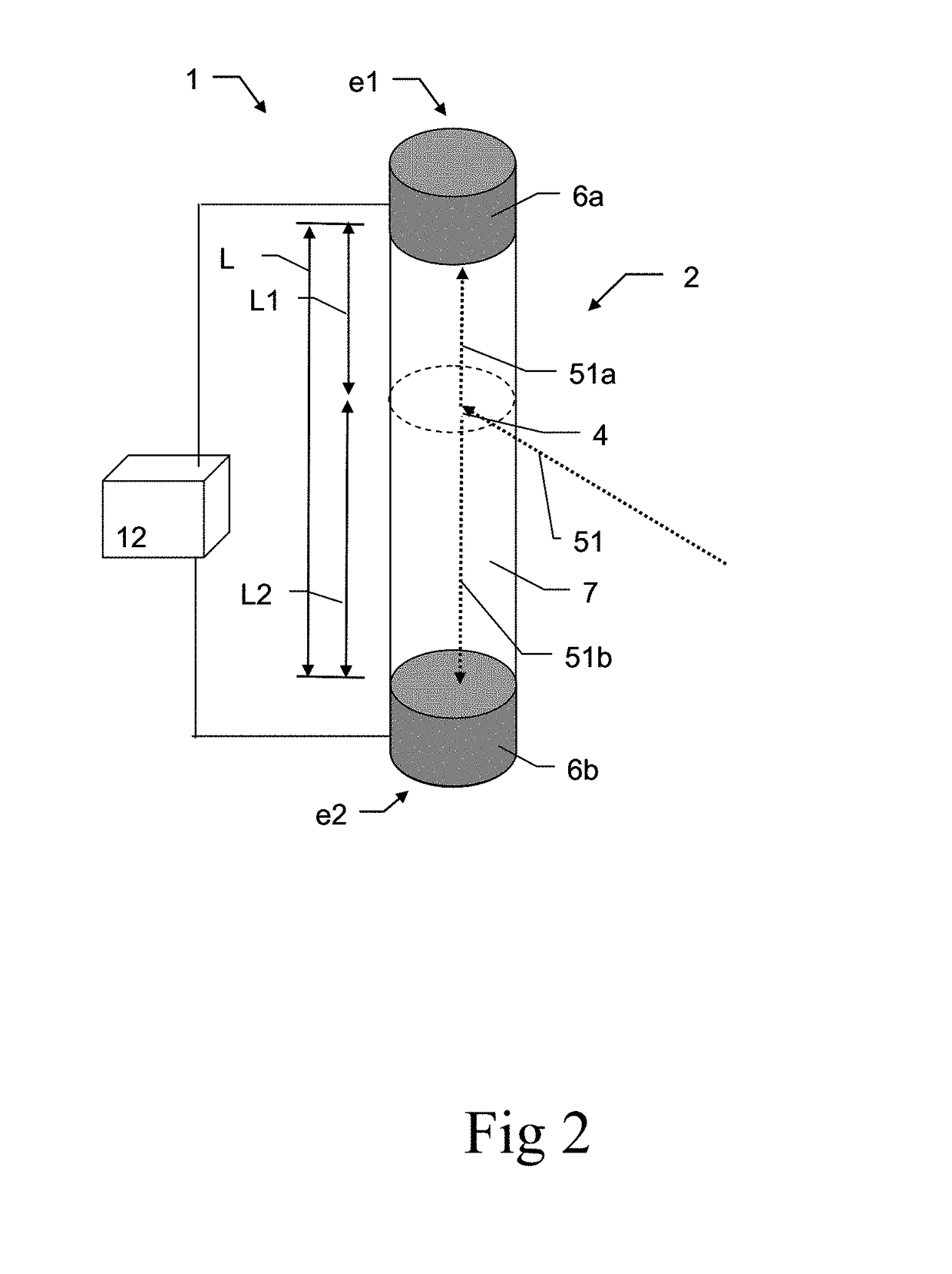
[0034]FIG. 1a shows an exemplary measuring system 50 according to the invention. In the example, the measuring system 50 is used for concrete working, where a plane concrete surface 101 has to be built, such as a building's ceiling. The system comprises a light emitter 52, e.g. a construction laser, that emits a laser light beam 51 of a light source such a as a laser source or SLED with a well defined direction of emittance as reference light, thus serving as a position reference. In the example, the direction of emittance is strictly horizontal. The system 50 further comprises a light receiver 1 spaced apart from the construction laser 52 for receiving the reference light 51 and determine a position thereof. The light receiver 1 comprises a light receptor 2 arranged on a support 100 of defined length and a signal processor (not shown) for processing signals of the light receptor 2. The signal of the light receptor 2 varies with the impinging position 4 of the reference light 51 and...


PUM


Abstract

A light receiver designed to determine a position or orientation relative to a reference light wherein the light receiver comprises an elongated rod-shaped light receptor with two ends, a light coupler, a light guide, and light detection means at both ends and a signal processor to process the electric signals of the detection means and to determine the relative position and/or orientation by a comparative evaluation of the electric signals. The light guide serves as a light propagation path of defined length for light coupled into the light guide by the light coupler and the signal processor determines the position and/or orientation based on light propagation speed of the reference light propagating in the light guide.

Description

CROSS-REFERENCE TO RELATED APPLICATIONS[0001]This application claims priority to European Patent Application No. 17171832 filed on May 18, 2017. The foregoing patent application are incorporated herein by reference.FIELD OF INVENTION[0002]The present invention relates to a light receiver to determine a position and / or orientation relative to a reference light, a position measuring system, and a position determination method.BACKGROUND[0003]A measurement task often occurring in practice is the determination of the absolute or relative position in space of a point or an object. This is required, for example in construction work, surveying tasks, building and operation of heavy machinery, or the monitoring of relative displacement in buildings, bridges, tunnels, dams, etc. Traditionally, this measurement problem is solved with known instruments such as levelling boards, surveyor's staffs, measuring rods or rulers. These instruments rely on a human observer to determine the relative pos...

Claims


Application Information

Patent Timeline
IPC IPC(8): G01C15/00G01C3/08
CPCG01C15/006G01C3/08G01C15/002G01J1/0425G01J1/0407G01J2001/0496G01J1/0488G01J1/0474G01J1/4228G01J2001/4238G01J1/4257
Inventor SEITZ, PETERAMMER, THOMASHINDERLING, JURG
Owner LEICA GEOSYSTEMS AG
Why Eureka
Try Eureka