Flue gas desulfurization device and process

A desulfurization device and flue gas technology, applied to the separation of dispersed particles, chemical instruments and methods, separation methods, etc., to achieve the effects of stable operation, low energy consumption, and no secondary pollution

Active Publication Date: 2014-01-01
ZHONGBEI UNIV
View PDF7 Cites 13 Cited by
  • Summary
  • Abstract
  • Description
  • Claims
  • Application Information

AI Technical Summary

Problems solved by technology

[0004] In order to solve the above-mentioned problems existing in the ex

Method used


Image

  • Flue gas desulfurization device and process
  • Flue gas desulfurization device and process
  • Flue gas desulfurization device and process

Examples


Embodiment 1

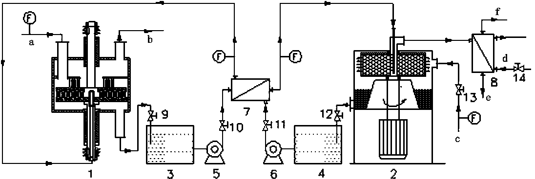
[0056] Example 1: Set the upper and lower turntables of the rotary packed bed absorber 1 to rotate in reverse, the speed is 400 r / min, the concentration of sodium hydrogen phosphate buffered aqueous solution is 1 mol / L (expressed as phosphate radical), and the pH is 6.5. SO in flue gas 2 The concentration is 0.2%, the flue gas flow rate is 150m3 / h, the liquid-gas ratio is 0.8 L / m 3 , the absorption reaction temperature is 35°C, and the flue gas desulfurization rate is higher than 99.1%. The absorbed rich liquid is desorbed by the rotary packed bed desorber 2, the speed of the desorber is 600 r / min, the temperature of the water vapor is 112°C, the temperature of the desorption operation is 97°C, and the gas-liquid ratio is 600m 3 / m 3 , the desorption rate of the rich solution is higher than 92%.

Embodiment 2

[0057] Example 2: Set the upper and lower turntables of the rotary packed bed absorber 1 to rotate in reverse, the rotation speed is 600 r / min, the concentration of the sodium phosphate buffer solution is 0.5 mol / L (expressed as phosphate radical), the pH is 5.6, and the smoke SO in air 2 The concentration is 0.06%, and the flue gas flow rate is 120 m 3 / h, the liquid-gas ratio is 0.6 L / m 3 , the absorption reaction temperature is 35°C, and the flue gas desulfurization rate is higher than 99.3%. The absorbed rich liquid is desorbed by the rotary packed bed desorber 2, the speed of the desorber is 550 r / min, the temperature of the water vapor is 109°C, the temperature of the desorption operation is 98°C, and the gas-liquid ratio is 500m 3 / m 3 , the desorption rate of the rich solution is higher than 93%.

Embodiment 3

[0058] Example 3: Set the upper and lower turntables of the rotary packed bed absorber 1 to rotate in reverse, the rotation speed is 600 r / min, the concentration of the sodium phosphate buffer solution is 1.5 mol / L (expressed as phosphate radical), the pH is 6.0, and the smoke SO in air 2 The concentration is 1%, and the flue gas flow rate is 150 m 3 / h, the liquid-gas ratio is 3 L / m 3 , the absorption reaction temperature is 40°C, and the flue gas desulfurization rate is higher than 99.4%. The absorbed rich liquid is desorbed by the rotary packed bed desorber 2, the speed of the desorber is 800 r / min, the temperature of the water vapor is 115°C, the temperature of the desorption operation is 97°C, and the gas-liquid ratio is 600 m 3 / m 3 , the desorption rate of the rich solution is higher than 95%.


PUM


Abstract

The invention belongs to the technical field of flue gas desulfurization, and particularly relates to a flue gas desulfurization process and device, which aim to solve the problems of an existing flue gas desulfurization process and device. The flue gas desulfurization device comprises a retrograde rotation packed bed absorber, a rotation packed bed desorber, a barren liquid storage groove, a rich liquid storage groove, a barren liquid circulation pump, a rich liquid circulation pump, a heat exchanger and a condenser. The flue gas desulfurization process comprises an absorption process and a desorption process. The device provided by the invention is small in size, has a wide in treatment gas quantity range, and is simple in structure and easy to operate. The process has the advantages of high desulfurization rate, low energy consumption, simple process, low investment and running expense, running stability, convenience in starting and stopping and the like.

Description

technical field [0001] The invention belongs to the technical field of flue gas desulfurization, and in particular relates to a flue gas desulfurization device and process. Background technique [0002] SO 2 The control of emissions has always been the focus of environmental governance around the world, and 90% of SO 2 It comes from the combustion of fuel, so flue gas desulfurization technology is widely used. At present, more than 200 flue gas desulfurization technologies have been researched, developed and used in various countries, of which about 20 have been industrialized, and the wet desulfurization technology with the advantages of large gas processing capacity and high efficiency is the main one. Most of its principles are based on Alkaline absorbent absorbs SO in flue gas 2 , such as lime / limestone / gypsum method, ammonia method, double alkali method, etc., but the desulfurization products of these methods have complex components and low utilization rate. If t...

Claims


Application Information

Patent Timeline
IPC IPC(8): B01D53/78B01D53/50B01D53/96
Inventor 袁志国刘有智祁贵生焦纬洲申红艳张巧玲高璟栗秀萍王建伟
Owner ZHONGBEI UNIV
Why Eureka
Try Eureka