Screen surface distributing device of vibrating screen

A material distributing device and vibrating screen technology, which is applied in the direction of filter screen, solid separation, grille, etc., can solve the problems that cannot meet the effective area of ​​the screen surface of the vibrating screen, energy loss, spare parts loss, etc.

Active Publication Date: 2014-01-01
BAOSHAN IRON & STEEL CO LTD
View PDF8 Cites 6 Cited by
  • Summary
  • Abstract
  • Description
  • Claims
  • Application Information

AI Technical Summary

Problems solved by technology

When the material enters the chute through the head of the belt conveyor, 50% of the effective area of ​​the material on the belt conveyor enters the 1200mm chute guide groove, and the material area on the belt conveyor is 50%, so that the material passing through the lining plate of the chute body cannot be distributed normally. Even if the distribution is normal, the discharge of the material guide trough is 1200mm, and the size of the screen surface of the vibrating screen is 2140mm, which cannot meet the effective area of ​​the screen surface of the vibrating screen.
[0006] 2. Uneven material distribution on the screen surface of the vibrating screen causes blockage of the mesh in the middle of the screen
[0007] Because the width of the outlet of the chute and the screen surface of the vibrating screen is inconsistent, the effective area of ​​the material entering the screen surface of the vibrating screen forms a trapezoid, and the effective area of ​​the screen surface of the vibrating screen cannot be fully utilized. Thick material layer in the middle of upper distribution and thin material layer on both sides will cause the mesh of the vibrating screen to be clogged, frequent cleaning of accumulated material on the screen, and reduced screening effect
[0008] 3. The screen surface of the vibrating screen is thicker in the middle material layer and thinner on both sides. The worn materials in the middle screen are concentrated on the middle screen of the vibrating screen. The friction force of the material on the screen increases, and the wear in the middle of the screen is ob

Method used


Image

  • Screen surface distributing device of vibrating screen
  • Screen surface distributing device of vibrating screen
  • Screen surface distributing device of vibrating screen

Examples


Embodiment Construction

[0025] The technical solutions of the present invention will be further described below in conjunction with the accompanying drawings and embodiments.

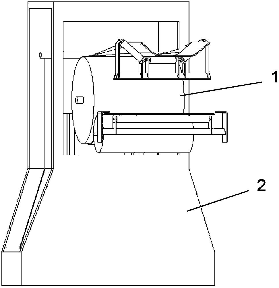
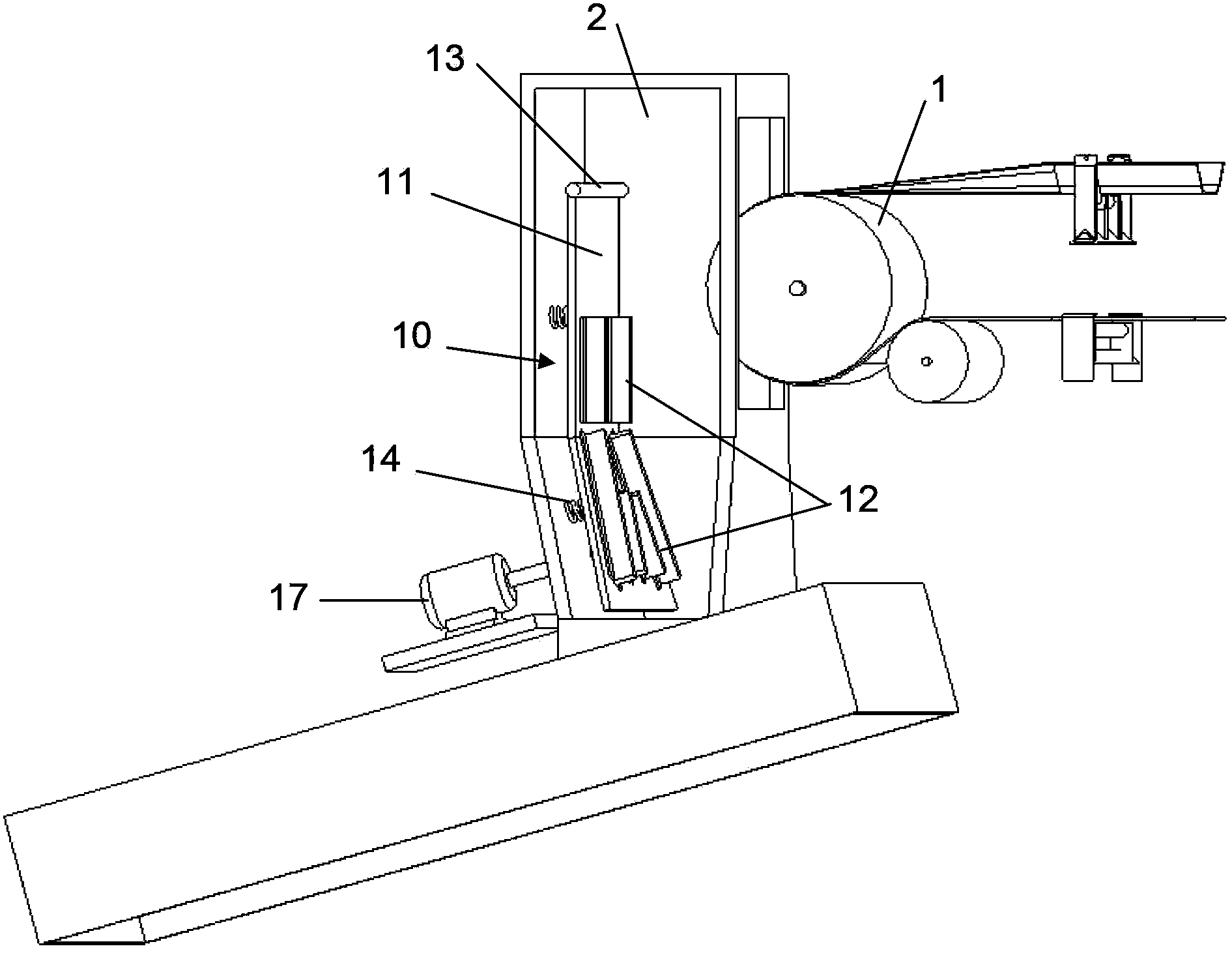
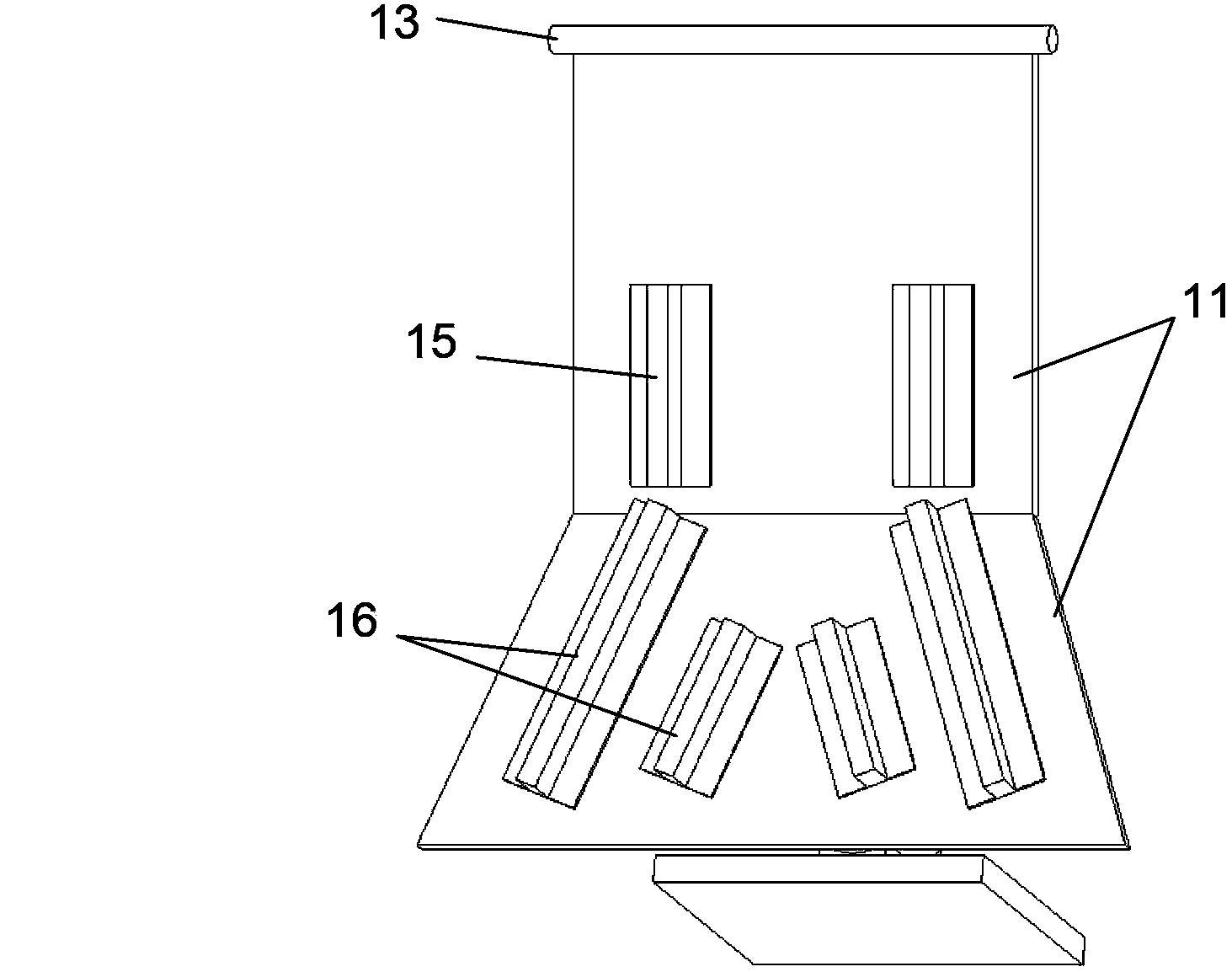
[0026] Please combine Figure 2 ~ Figure 4 As shown, the vibrating screen surface distributing device 10 of the present invention is arranged in the chute 2 at the head of the belt conveyor 1 and is located on the vibrating screen 3 . What needs to be explained next is that, in order to fully consider the volume and installation position of the material guide plate 11 and the material distributor 12, the lower part of the chute 2 of the belt conveyor 1 is modified before installation so that the discharge port of the vibrating screen 3 It is advisable to match the width of the screen mesh so as not to affect the normal operation of the vibrating screen 3. For example: in the ore crushing and screening system, the width of the outlet of the chute 2 of the K105 belt conveyor 1 is 1200mm, while the size of the screen surface of ...


PUM


Abstract

The invention discloses a screen surface distributing device of a vibrating screen. The distributing device comprises a self-vibrating guiding plate and a material allocator, wherein the guiding plate is distributed along a chute and comprises a vertical section and an inclined section, the upper end of the vertical section is fixed, the lower end of the vertical section is connected with the upper end of the inclined section, the back surface of the guiding plate is provided with a plurality of self-vibrating springs which are connected with the chute, the material allocator comprises a vertical separation plate which is arranged on the vertical section and a plurality of pairs of splayed separation plates which are arranged on the inclined section. Through the function of the self-vibrating guiding plate and the material allocator, the material accumulation inside the chute can be reduced, the adequate and uniform distribution of the material after entering the guiding plate can be guaranteed, and the uniform distribution of the material on the screen surface of the vibrating screen can be realized.

Description

technical field [0001] The invention relates to a vibrating screen, more specifically, to a vibrating screen screen surface distributing device. Background technique [0002] The vibrating screen is a continuous screening mechanical equipment in the system, which is mainly used to deal with the particle size separation of materials. At present, it has become a common screening equipment in industrial and agricultural production, especially widely used in metallurgy, mining, coal and so on. There are more than 20 vibrating screen equipment in the raw material ore crushing system of metallurgical enterprises, which are responsible for the processing of blast furnace concentrate ore. During the material screening process of the vibrating screen, due to the uneven distribution of the material by the belt conveyor chute of the system, the quality of the finished product of ore crushing and screening is affected. The impact of ore powder content on blast furnace smelting, in the...

Claims


Application Information

Patent Timeline
IPC IPC(8): B07B1/46B07B1/28
Inventor 李根良杨斌李刚沈源丰
Owner BAOSHAN IRON & STEEL CO LTD
Why Eureka
Try Eureka