
Automatic feeding device, automatic feeding-type punch press and automatic feeding method

A technology of automatic feeding and feeding, which is applied in the field of punching machines, can solve the problems of the limitation of the moving distance of the feeding manipulator and the material receiving manipulator of the sheet size, the lengthening of the moving distance of the feeding manipulator and the material receiving manipulator, and the increase of the labor intensity of the operator, etc., so as to save time Cost and labor costs, convenient operation, and promotional effects

Inactive Publication Date: 2014-01-01
HANGZHOU KINGNET ELECTROMECHANICAL
View PDF7 Cites 17 Cited by
  • Summary
  • Abstract
  • Description
  • Claims
  • Application Information

AI Technical Summary

Problems solved by technology

Although the automatic feeding equipment of this utility model patent can complete blank blanking at one time, there are still many problems: 1. The size of the blank is limited by the moving distance of the feeding manipulator and the material receiving manipulator
Since the feeding manipulator is installed in the feeding mechanism and the receiving manipulator is installed in the receiving manipulator, the moving distance between the feeding manipulator and the receiving manipulator limits the length of the sheet to be processed. If the sheet to be processed is too long, A large unprocessed sheet area is left on the sheet. If these unprocessed sheet areas are too short, they cannot be placed in the equipment for punching.
This not only limits the size and length of the sheet, but also wastes a lot of materials, which is not very practical
2. If it is necessary to process some relatively long sheets, the feeding mechanism and the receiving mechanism need to be lengthened correspondingly, and the moving distance of the feeding robot and the receiving robot should also be lengthened
This not only increases the labor intensity of the operator, but also brings a lot of inconvenience to the repair of the mold.

Method used


Image

  • Automatic feeding device, automatic feeding-type punch press and automatic feeding method
  • Automatic feeding device, automatic feeding-type punch press and automatic feeding method
  • Automatic feeding device, automatic feeding-type punch press and automatic feeding method

Examples


Embodiment 1

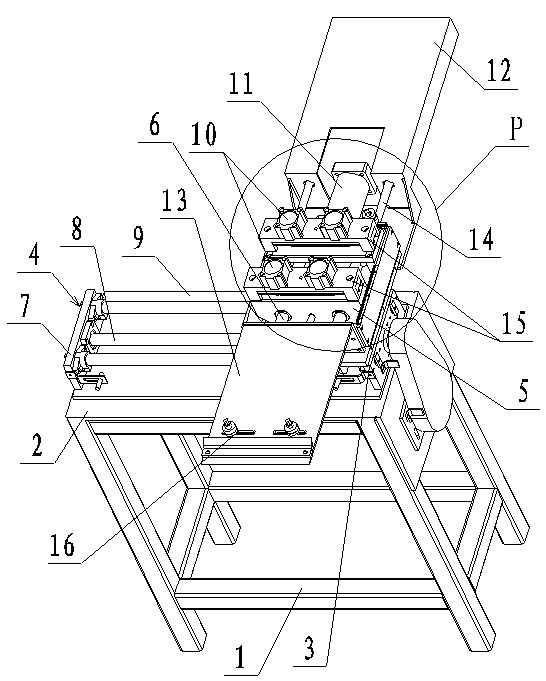
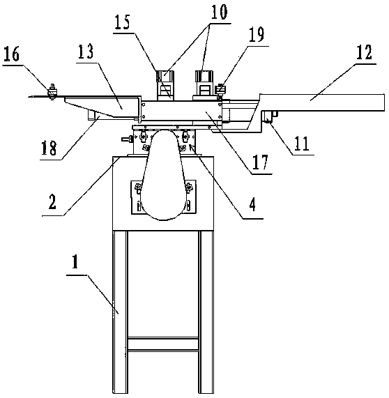
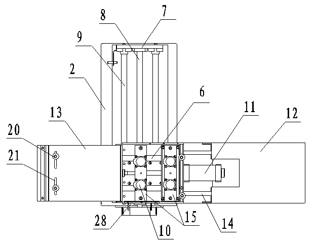
[0039] Embodiment 1: with reference to attached Figure 1-4 . An automatic feeding device, comprising a bracket 1; a worktable 2 is arranged on the top surface of the support 1; a screw drive mechanism 4 placed in the Y direction is installed on the worktable 2; the screw drive mechanism 4 includes a Y-direction screw rod 8, The motor (not shown in the figure) that controls the Y-direction screw rod 8, the fixed plate 7 fixed on the two ends of the Y-direction screw rod 8, the screw guide rail 9 between the fixed plates 7; the screw drive mechanism 4 is also provided with Sliding seat 3; sliding seat 3 slides on the screw mandrel guide rail 9 with the rotation of the Y-direction screw mandrel 8; the sliding seat 3 is provided with a fixed frame 17; the fixed frame 17 is provided with a guide rail 6 and a fixed bracket 25; Slide rail 6 is perpendicular to screw mandrel guide rail 9; Guide slide rail 6 passes fixed support 25, and the two ends of guide slide rail are fixed in f...

Embodiment 2

[0040] Embodiment 2: on the basis of embodiment 1, with reference to appended Figure 5 . A kind of automatic feeding type punching press, comprises punching press 23 and the mold 22 that is positioned at punching press 23; The automatic feeding device described in embodiment 1 is two, and is installed in the mold 22 both sides of punching press 23 respectively in alignment; Two automatic feeding devices The motors of the feeding device are all controlled by the control system of the electric control cabinet; the guide plates B13 of the two automatic feeding devices are all facing each other and are arranged on both sides of the mold 22 .

[0041] In the above-mentioned automatic feeding punching machine, the feeding cylinder A11 and the feeding cylinder B18 on the automatic feeding device can be designed as fixed-range push rod cylinders, so that the position of each blanking of the sheet can be controlled more accurately, and the blanking accuracy of the workpiece can be imp...

Embodiment 3

[0042] Embodiment 3: on the basis of embodiment 2, with reference to appended Figure 6 . Adopt the punch press among the embodiment 2, the method for automatic feeding, with processing attached Figure 6 The artifact shown in , as an example, includes the following steps.

[0043] (1) Calculate the displacement of the sheet.

[0044] ① Before processing, design the arrangement of the workpieces on the sheet according to the size of the sheet, aiming at punching the maximum number of workpieces on a sheet, saving the sheet and cost;

[0045] ②According to the arrangement of workpieces on the sheet, measure and calculate the moving coordinates (X, Y) of the sheet when punching the first workpiece;

[0046] ③According to the arrangement of the workpieces on the sheet in step ①, measure and calculate the distance L of adjacent workpieces in the X direction, the distance S of adjacent workpieces in the Y direction, and the dislocation distance K; use the Y-direction group punch...


PUM


Abstract

The invention relates to an automatic feeding-type punch press which comprises automatic feeding devices. The automatic feeding devices are mounted on two sides of a die of the punch press in an alignment manner respectively. Each automatic feeding device comprises a support provided with a worktop on the top face; sliding seats are arranged on screw rod transmission mechanisms mounted on the worktops; feeding sliders are mounted on the sliding seats through guide sliding rails perpendicular to the screw rod transmission mechanisms; plate fixing devices are arranged above the feeding sliders; each feeding slider slides on the corresponding guide sliding rail through two feeding cylinders respectively arranged on two sides of the feeding slider; motors of the automatic feeding devices are controlled by a control system of an electrical control cabinet to drive the screw rod transmission mechanisms to enable the sliding seats to slide, and the feeding cylinders are utilized to control the feeding sliders to slide to complete automatic feeding of plates. The automatic feeding-type punch press is adopted to punch workpieces, the automatic feeding devices are simple in structure, small in occupied space and applicable to processing of various plates, and the die of the punch press is convenient to maintain and easy for workers to operate.

Description

technical field [0001] The invention relates to an automatic feeding device, in particular to an automatic feeding device installed on a punching machine to realize automatic feeding, and belongs to the technical field of punching machines. Background technique [0002] In the stamping industry, in order to improve the blanking processing efficiency of the workpiece and avoid safety accidents caused by operator errors during the feeding process, most manufacturers in the industry use automatic feeding devices. For example, the Chinese patent No. ZL200910213861.7 discloses an automatic feeding mechanism, which includes a frame, a worktable on the frame, a screw installed under the worktable, a servo motor for controlling the rotation of the screw, The push claw seat moving on the screw rod, the push claw installed on the push claw seat and the iron plate installed on the worktable, the sheet material is located between the iron plate and the worktable, the servo motor control...

Claims


Application Information

Patent Timeline
Patent Type & Authority Applications(China)
IPC IPC(8): B21D43/02B21D43/00
Inventor 张海农
Owner HANGZHOU KINGNET ELECTROMECHANICAL
Learn More