
Wide field image space telecentric optical system of three-line-array three-dimensional aerial survey camera

An optical system and aerial survey camera technology, applied in the field of aerial remote sensing and surveying and mapping, can solve the problems of high technical difficulty and high usage requirements, and achieve the effects of high resolution, large field of view, good illumination uniformity and color reproduction

Active Publication Date: 2014-01-01
XI'AN INST OF OPTICS & FINE MECHANICS - CHINESE ACAD OF SCI
View PDF5 Cites 8 Cited by
  • Summary
  • Abstract
  • Description
  • Claims
  • Application Information

AI Technical Summary

Problems solved by technology

[0011] At present, the three-dimensional aerial camera for linear array detectors is still blank in China. The three-line array three-dimensional aerial camera system needs a large field of view, high resolution, and high-precision optical system, which has high requirements for use and great technical difficulties. There is no such optical system in China

Method used


Image

  • Wide field image space telecentric optical system of three-line-array three-dimensional aerial survey camera
  • Wide field image space telecentric optical system of three-line-array three-dimensional aerial survey camera
  • Wide field image space telecentric optical system of three-line-array three-dimensional aerial survey camera

Examples


Embodiment Construction

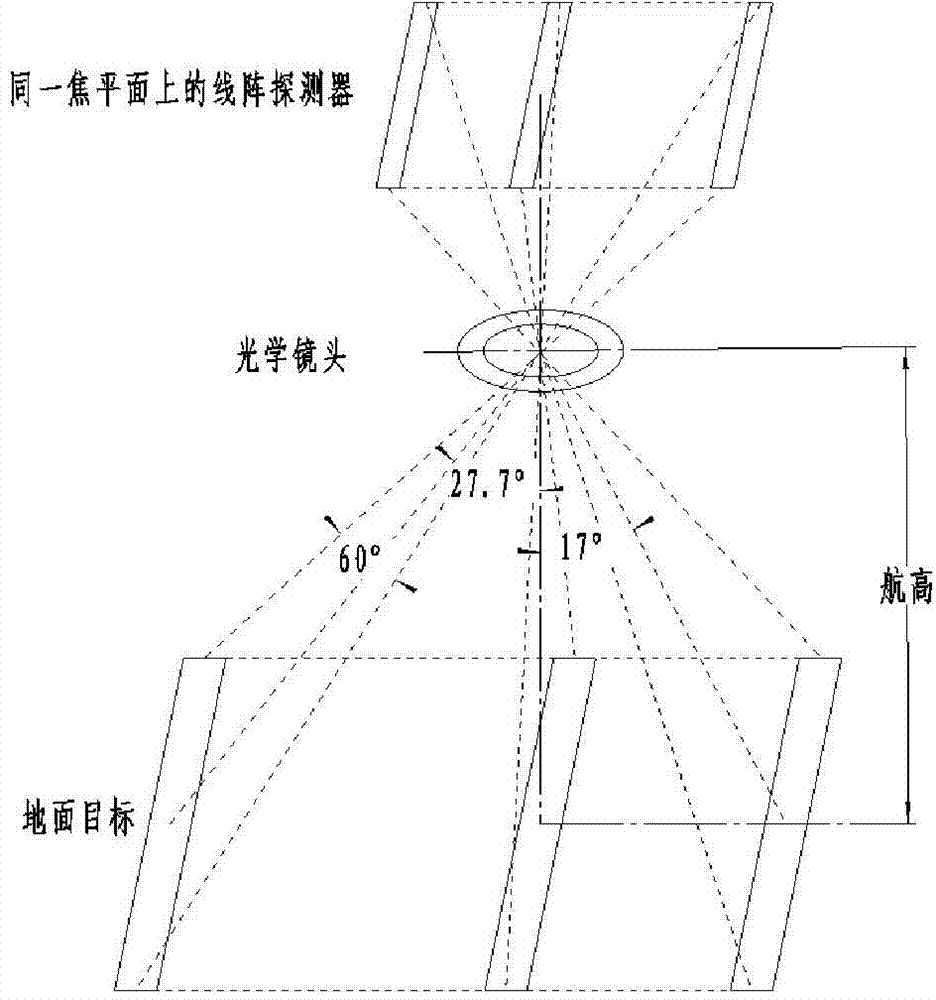
[0048] The wide field of view telecentric three-line array stereoscopic aerial survey camera uses aircraft pushbroom to image the ground target on the front-looking, down-looking, and rear-looking array detectors located on the image plane. The main performance indicators of its optical system are:

[0049] 1. The working band is 0.45μm~0.75μm;

[0050] 2. The focal length of the system is 130mm

[0051] 3. The field of view is 77°

[0052] 4. The working field of view is 60° (with the line array detector, the width direction of a single solid angle)

[0053] 5. The relative aperture is 1 / 5

[0054] 6. Detector spatial frequency 77lp / mm

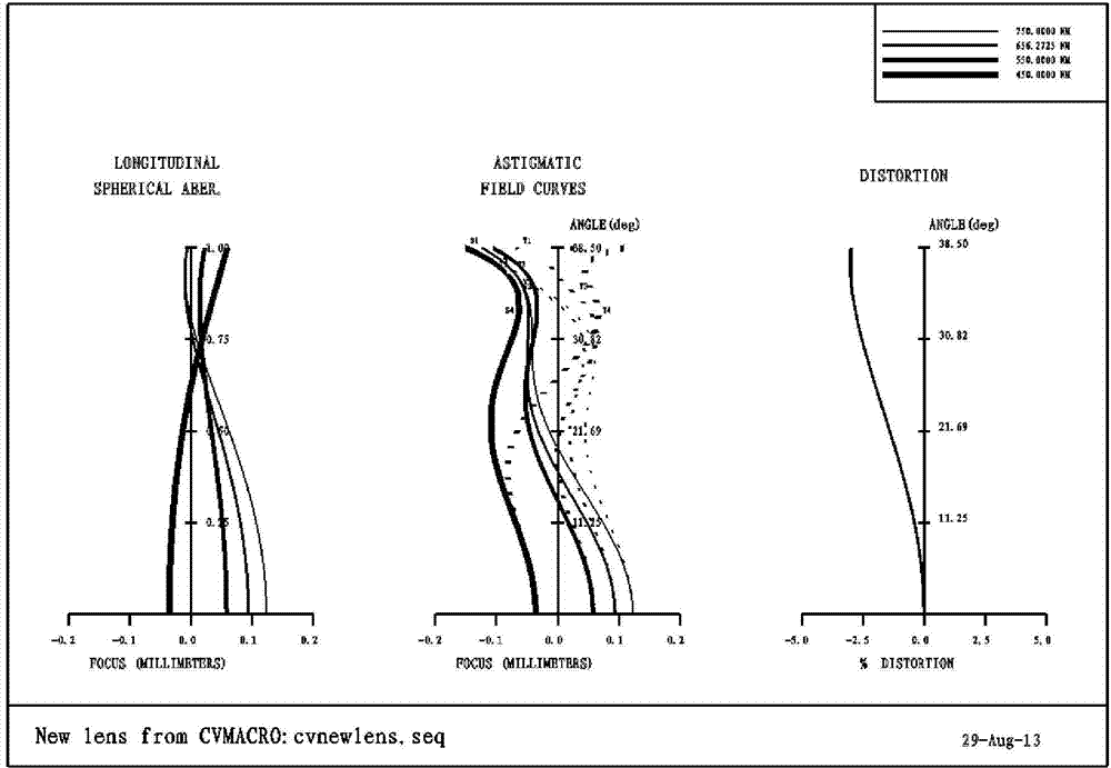
[0055] 7. Distortion≤3%

[0056] 8. Image side telecentric optical path structure, telecentricity ≤ 0.1°

[0057] 9. Optical transfer function MTF 0 field of view>0.63 (77lp / mm)

[0058] 0.7 field of view>0.46 (77lp / mm)

[0059] 1 field of view>0.32 (77lp / mm)

[0060] 10. Base height ratio 0.83, imaging solid angle 27.7°, 0°, 17°

[...


PUM


Abstract

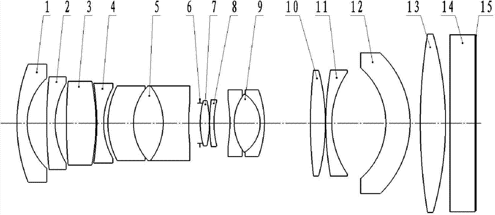
The invention provides a wide field image space telecentric optical system of a three-line-array three-dimensional aerial survey camera. The optical system comprises a first negative lens, a second negative lens, a first positive lens, a third negative lens, a first three-bonding-lens set, a diaphragm, a second positive lens, a fourth negative lens, a second three-bonding-lens set, a third positive lens, a fifth negative lens, a sixth negative lens, a fourth positive lens and a multi-spectral beam splitting system equivalent panel, wherein the first negative lens, the second negative lens, the first positive lens, the third negative lens, the first three-bonding-lens set, the diaphragm, the second positive lens, the fourth negative lens, the second three-bonding-lens set, the third positive lens, the fifth negative lens, the sixth negative lens, the fourth positive lens and the multi-spectral beam splitting system equivalent panel are arranged along a same optical axis in sequence. The second positive lens, the fourth negative lens, the third positive lens, the fifth negative lens, the sixth negative lens, the fourth positive lens and the multi-spectral beam splitting system equivalent panel form a rear lens set together, and the diaphragm is located on the front focal plane of the rear lens set. A negative lens-positive lens-negative lens structural form is adopted in the first three-bonding-lens set, and the negative lens-positive lens-negative lens structural form is adopted in the second three-bonding-lens set. The wide field image space telecentric optical system of the three-line-array three-dimensional aerial survey camera has the advantages of being wide in view of field, high in resolution, telecentric in image space and the like.

Description

technical field [0001] The invention belongs to the technical field of aerial remote sensing and surveying and mapping, and relates to an optical system applied to a new optical load of aerial earth observation. Background technique [0002] The three-line array stereoscopic aerial survey camera is installed on the aircraft platform. Through the push-broom of the aircraft, three linear array detectors on the focal plane are used to obtain the front-view, down-view, and rear-view images of the same ground object, and finally the three-dimensional ground object is obtained by using image processing technology. digital imaging. [0003] As a hotspot in foreign research, the three-line array stereoscopic aerial survey digital camera has always attracted the attention of all parties. There are also two ways of its technical realization, namely, the single-lens internal splicing form and the three-lens external splicing form. Representatives of single-lens internal stitching tech...

Claims


Application Information

Patent Timeline
Patent Type & Authority Applications(China)
IPC IPC(8): G02B13/18G02B13/00G02B13/06G02B13/22G01C11/02
Inventor 闫阿奇张建周祚峰武登山冷寒冰曹剑中张凯胜
Owner XI'AN INST OF OPTICS & FINE MECHANICS - CHINESE ACAD OF SCI
Learn More