Stator division type axial flux switching type mixed excitation synchronous motor

A hybrid excitation synchronous, axial magnetic flux technology, applied in electrical components, electromechanical devices, etc., can solve the problems of irreversible demagnetization of permanent magnets, reduced motor operating efficiency, and low utilization rate of permanent magnets, so as to reduce the risk of demagnetization, reduce the risk of motor The effect of improving efficiency and increasing the relative overlapping area

Inactive Publication Date: 2014-01-01
JIANGXI UNIV OF SCI & TECH
View PDF2 Cites 17 Cited by
  • Summary
  • Abstract
  • Description
  • Claims
  • Application Information

AI Technical Summary

Problems solved by technology

[0005] The dual-rotor axial flux switching hybrid excitation synchronous generator with application number 200910186156.2 discloses an axial flux switching hybrid excitation motor with permanent magnets located on the stator. However, its excitation winding is directly wound on the surface of the permanent magnet, and the permanent magnet The magnetic potential and the electric excitation magnetic potential are in a series state. When the motor is working, the heat generated by the current in the excitation winding will cause the temperature of the permanent magnet to ri

Method used


Image

  • Stator division type axial flux switching type mixed excitation synchronous motor
  • Stator division type axial flux switching type mixed excitation synchronous motor
  • Stator division type axial flux switching type mixed excitation synchronous motor

Examples


Embodiment Construction

[0028] Below in conjunction with accompanying drawing, the present invention is described in further detail:

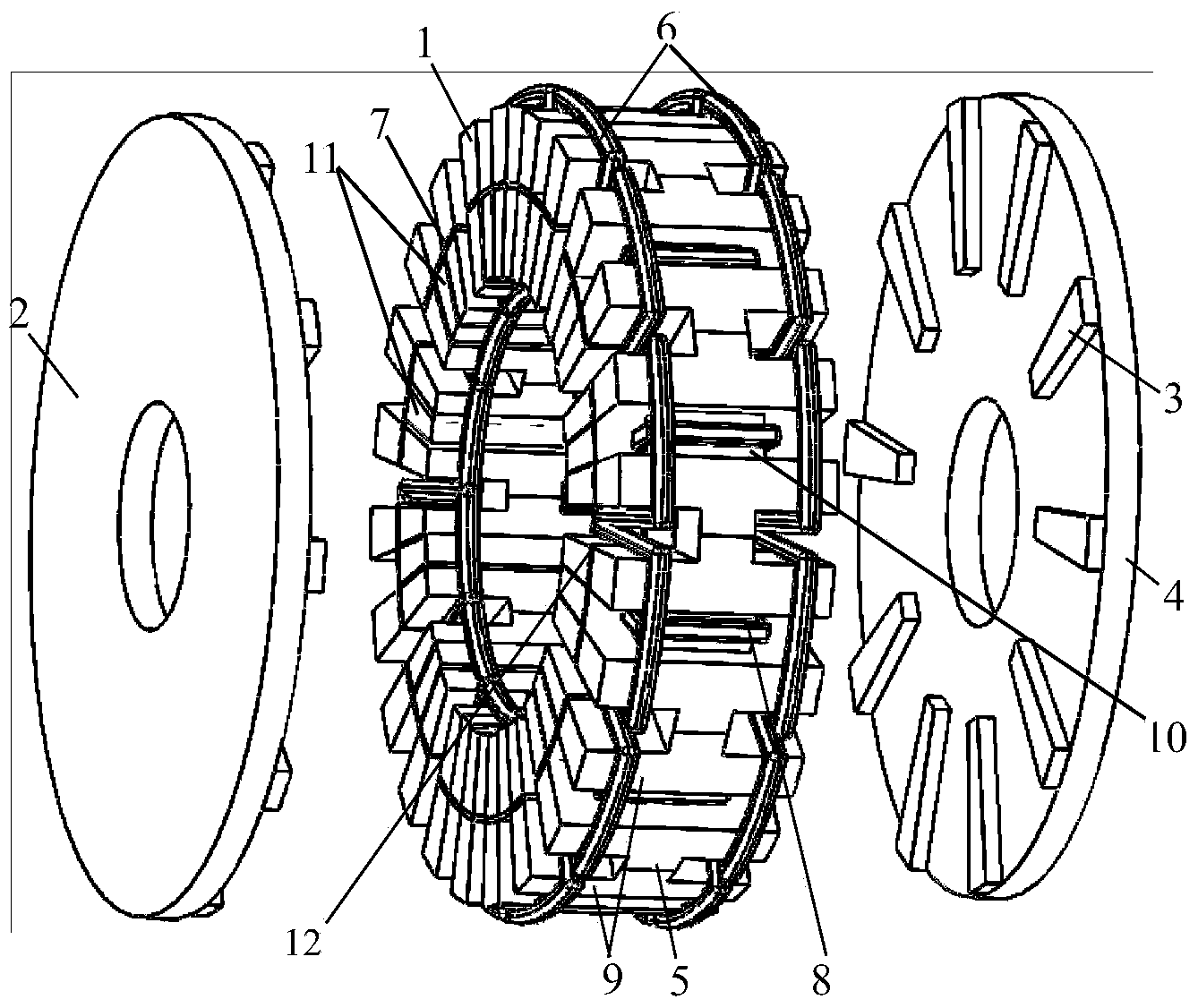
[0029] Such as figure 1 as shown,

[0030]A stator-divided axial flux switching hybrid excitation synchronous motor, which is composed of a stator 1 and a rotor 2, is characterized in that the stator is spliced ​​into two winding concentric circles by splicing the inner and outer layers of "H"-shaped unit stator cores 5 The two concentric rings are separated by a magnetic isolation ring 7, and the armature winding 6 adopts a concentrated winding, and the armature winding 6 is wound on the stator teeth 9 of two adjacent "H" type unit stator cores 5, and the permanent magnet 11 is formed The N and S poles are distributed in the middle of the stator core 5 of the adjacent "H" type unit, and the permanent magnet 11 is tangentially magnetized; the permanent magnet 11 and the stator slot 12 both adopt a rectangular structure; the excitation bracket 10 is located directly a...


PUM

PropertyMeasurementUnit
Thicknessaaaaaaaaaa

Abstract

A stator division type axial flux switching type mixed excitation synchronous motor comprises a stator and a rotor. According to the stator, an inner layer H-shaped unit stator iron core and an outer layer H-shaped unit stator iron core are connected to form two wound concentric rings in a splicing mode, a magnetism separation ring separates the two concentric rings, armature windings are concentrated windings and wind stator teeth of the two adjacent H-shaped unit stator iron cores, permanent magnets are distributed between the adjacent H-shaped unit stator iron cores in an N-pole-and-S-pole-alternating mode. The permanent magnets and a stator groove are of a rectangular structure. An excitation support is placed right above the permanent magnets and is separated by the magnetism separation ring. An excitation winding winds the excitation support axially. The rotor is of a disc type structure and comprises a rotor magnet yoke and rotor poles which are evenly fixed on the surface of the rotor magnet yoke in a radial mode. The stator and the rotor are connected coaxially. The magnetism separation ring is used for separating the stator into an inner portion and an outer portion, so that an electro-magnetic circuit and a permanent magnet magnetic circuit are completely connected in parallel, coupling of the two magnetic circuits is lowered, using rate of the permanent magnets is greatly improved, and motor efficiency is obviously improved.

Description

technical field [0001] The invention relates to a stator split type axial magnetic flux switching hybrid excitation synchronous motor, which belongs to the technical field of motor manufacturing. Background technique [0002] The flux-switching permanent magnet motor is a stator permanent magnet motor. There is neither permanent magnet nor winding on the rotor, and the structure is simple; as the rotor position changes, the flux can automatically switch paths, so that the flux linkage in the stator winding Both direction and direction change, thus generating alternating induced electromotive force. This type of motor has the advantages of small size, light weight, reliable operation, convenient cooling, high power density and high efficiency. However, because the magnetic field cannot be adjusted, this type of motor is limited when used as a generator and motor. [0003] Hybrid excitation motor is a kind of flux-controllable permanent magnet synchronous motor. It not only ...

Claims


Application Information

Patent Timeline
IPC IPC(8): H02K37/02
Inventor 刘细平刁艳美左亮平黄朝志
Owner JIANGXI UNIV OF SCI & TECH
Why Eureka
Try Eureka