
Granular Polysilicon Fluidized Bed Reactor

A silicon fluidized bed and reactor technology, applied in chemical instruments and methods, silicon, chemical/physical processes, etc., can solve problems such as uneven wall-attached reactions, and achieve the effects of reasonable layout, improved product purity, and convenient control

Active Publication Date: 2015-07-29
江苏中圣压力容器装备制造有限公司
View PDF6 Cites 0 Cited by
  • Summary
  • Abstract
  • Description
  • Claims
  • Application Information

AI Technical Summary

Problems solved by technology

[0007] The purpose of the present invention is to design a granular polysilicon fluidized bed that utilizes microwave heating and hydrogen coverage to improve the efficiency and quality of polysilicon preparation in view of the problems of wall attachment and uneven reaction in the production of polysilicon particles by the existing fluidized bed method reactor

Method used


Image

  • Granular Polysilicon Fluidized Bed Reactor
  • Granular Polysilicon Fluidized Bed Reactor
  • Granular Polysilicon Fluidized Bed Reactor

Examples


specific example 1

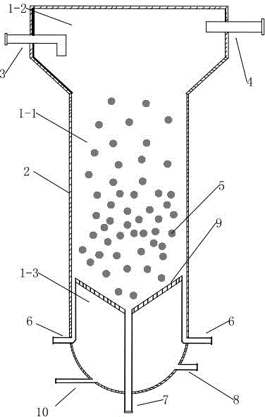
[0031] Specific example 1: Preheat the reaction raw material gas hydrogen and trichlorosilane to 700-800°C respectively, pass them into the gas buffer zone, and simultaneously pass the hydrogen covering gas into the reactor. The gas distributor 9 is used to pass part of the hydrogen into the reaction zone 1-1 along the wall, and the polysilicon seed preheated to 1000-1100 °C is passed into the reaction zone from the inlet 3 with the feed device. At this time, the reaction gas The temperature of the polysilicon seed crystal is kept at 1000-1100°C by the heater. At this time, the hydrogen gas starts to reduce trichlorosilane in the atmosphere of 1000-1100°C, and the polysilicon produced continuously gathers in the On the polysilicon seed crystal, as the reaction proceeds, the polysilicon particles continuously increase to the size set by the process, and then fall to the product collection device due to gravity. The product collection device is filled with inert gas to prevent o...

specific example 2

[0032] Specific example 2: Preheat the silane in the reactor to 500-600°C and then pass it into the gas buffer zone, and at the same time, cover the hydrogen gas into the reaction zone through the gas distributor. Use the gas distributor 8 to pass part of the hydrogen into the reaction zone along the inner wall of the reactor, and use the feeding device to introduce the silicon seed preheated to 700-800 °C into the reaction zone, and at this time, it is suspended in the reaction zone under the blowing of the reaction gas. In the zone, the surface temperature of the seed crystal particles is kept at 700-800°C by a heater, and silane gas is introduced. At this time, the silane gas decomposes in an atmosphere of 700-800°C, and decomposes to produce silicon and hydrogen. The produced silicon is continuously deposited on the surface of the silicon seed crystal. As the reaction progresses, the silicon particles continue to grow to the size set by the process, and fall into the pro...


PUM


Abstract

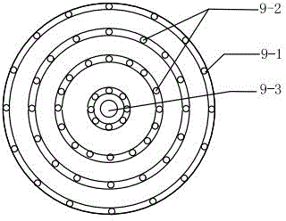
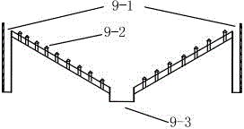
A granular polycrystalline fluidized bed reactor is characterized by comprising a gas discharge area (1-2), a reaction area (1-1) and a gas buffer area (1-3). The gas discharge area (1-2) is located on the upper portion of the reaction area (1-1) and in direct communication. The gas buffer area (1-3) is located on the lower portion of the reaction area (1-1) and separated from the same through a gas distributor (9). The center of the gas distributor (9) is provided with a discharge outlet (9-3) allowing product particles to be discharged out of the reactor. A hydrogen coverage gas inlet (9-1) and a reaction gas inlet (9-2)are formed in the outer ring of the gas distributor (9). The gas buffer area (1-3) is provided with a raw material gas inlet (8) and a fluidizing gas inlet (10). A cylinder wall of the reaction area (1-1) is provided with a microwave heater (2-4). The gas discharge area (1-2) is provided with a seed crystal inlet (3) and a tail gas exhaust outlet (4). The granular polycrystalline fluidized bed reactor is simple in structure and free of wall attachment.

Description

technical field [0001] The invention relates to a semiconductor material manufacturing equipment, in particular to a polysilicon manufacturing equipment, in particular to a fluidized bed reactor for preparing granular polysilicon by using the principle of chemical vapor deposition. Background technique [0002] At present, the Siemens method and the improved Siemens method are the production methods that currently dominate. The Siemens method uses electrodes to heat silicon rods to about 1100°C in a chemical vapor deposition reactor, and trichlorosilane decomposes on the surface of silicon rods to deposit crystalline silicon. [0003] However, the Siemens method has the problems of high energy consumption and heavy pollution. The reasons are as follows: (1) The Siemens method produces polysilicon with low conversion rate and high energy consumption; (2) This method produces a large amount of silicon tetrachloride by-products, which are difficult to recycle use, ca...

Claims


Application Information

Patent Timeline
Patent Type & Authority Patents(China)
IPC IPC(8): B01J8/24C01B33/03
Inventor 郭宏新刘世平刘丰高辉李奇练绵炎
Owner 江苏中圣压力容器装备制造有限公司
Learn More