Motor train unit traction system powered by power packs and energy storage devices in mixed mode

An energy storage device and hybrid power supply technology, which is applied in the direction of traction driven by engines, AC induction motors, electric traction, etc., can solve problems such as braking energy consumption, energy waste, and the inability of EMUs to run satisfactorily. Acceleration performance, reduced power and size, and the effect of optimal acceleration performance

Active Publication Date: 2014-01-08
CHINA RAILWAYS CORPORATION +1
View PDF7 Cites 26 Cited by
  • Summary
  • Abstract
  • Description
  • Claims
  • Application Information

AI Technical Summary

Problems solved by technology

All EMUs with single electric traction cannot meet the requirements of running on non-electrified railways, and cannot perform self-rescue in time when the electrified section fails or the high-voltage system of the vehicle itself fails
[0003] In addition, in the current non-electrified road sections, the traditional centralized power supply trains use the thermal power source, that is, the centralized power supply traction of internal combustion locomotives. During the braking process, the braking energy is mainly consumed by braking resistors, resulting in a huge waste of energy.

Method used


Image

  • Motor train unit traction system powered by power packs and energy storage devices in mixed mode
  • Motor train unit traction system powered by power packs and energy storage devices in mixed mode
  • Motor train unit traction system powered by power packs and energy storage devices in mixed mode

Examples


Embodiment Construction

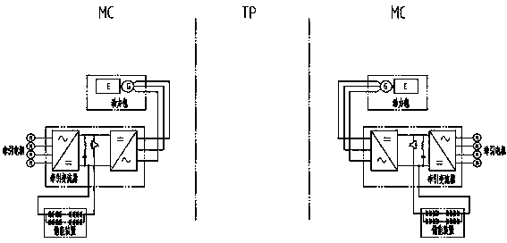
[0021] refer to figure 1 , the embodiment of the present invention includes a power pack, an energy storage device, a traction converter, and a traction motor, and the traction converter is connected to the traction motor; a diesel engine and a generator form an internal combustion power pack, and the three-phase output of the generator is directly connected to the traction converter The energy storage device is connected to the intermediate DC bus of the traction converter.

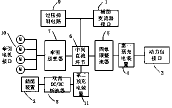
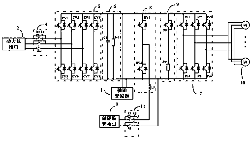
[0022] refer to figure 2 , image 3 , 1. Auxiliary converter interface 2. Power pack interface 3. Energy storage device interface 4. First pre-charging device 5. Four-quadrant rectifier 6. Intermediate DC link 7. Traction inverter 8. Bidirectional DC / DC chopper 9. Overvoltage suppression circuit 10. Traction motor interface 11. Second pre-charging device

[0023] The power pack interface 2 is connected to the input end of the four-quadrant rectifier 5, the energy storage device interface 3 is connect...


PUM


Abstract

A motor train unit traction system powered by power packs and energy storage devices in a mixed mode mainly comprises the power packs, the energy storage devices, traction converters and traction motors, wherein the traction converters are connected with the traction motors, a diesel engine and an electric generator form each internal combustion power pack, three-phase output of the electric generators are directly connected with the traction converters, and the energy storage devices are connected with middle direct-current buses of the traction converters. The motor train unit traction system can achieve cross-line running and meet different requirements for transportation in different environments. In a non-electrification road section, the power pack and energy storage device mixed power supply mode is adopted so that normal running under the working condition without a contact system can be achieved. Under the working condition that power is supplied by the power packs and no contact system exists, braking energy is absorbed through the energy storage devices, and therefore recycling of energy is achieved and the green energy saving concept is embodied. Power supplying can be achieved in the acceleration process of a train through the energy storage devices so that the optimum acceleration performance can be achieved. Due to the adoption of the energy storage devices, a power train unit can have the operating capacity in the non-electrification road section and have an emergency rescue function and a war preparedness function in special rainy and snowy days or under the condition that the contact system is damaged, and can also be used as a mobile power supply.

Description

technical field [0001] The invention relates to a traction system of an EMU, in particular to an electric traction system of an EMU in which a power pack and an energy storage device are mixed to supply power. Background technique [0002] The traction system is the core of the transmission system of the EMU, and it shoulders the task of providing driving power for the train. The traditional EMU traction system is mainly a single electric traction, which adopts catenary power supply mode and can only run on electrified railways. According to my country's railway planning, by the end of 2012, my country's electrified railways accounted for 53% of the country's railway lines; according to the "Medium and Long-Term Railway Network Planning", it is estimated that by 2020, electrified railways will account for 60% of the country's railway lines, and non-electrified railways will still a large proportion for a long time. All EMUs with single electric traction cannot meet the requ...

Claims


Application Information

Patent Timeline
Patent Type & Authority Applications(China)
IPC IPC(8): B60L11/18B60L50/15
CPCY02T10/7241Y02T10/7005B60L7/14B60L9/28B60L15/007B60L15/20B60L15/2045B60L50/13B60L2200/26B60L2210/12B60L2210/14Y02T10/64Y02T10/72
Inventor 赵明花李军王成涛王树宾荀玉涛李雪飞韩伟况阳哈大雷解枫周勇志马昭钰翟黎渊刘俊明万争田伟翟丽佳王颖超蒋英智张金龙金鑫
Owner CHINA RAILWAYS CORPORATION
Why Eureka
Try Eureka