
SCR denitration device and denitration method applicable to middle and small-size boilers

A technology for small and medium-sized boilers, which can be used in combination devices, separation methods, chemical instruments and methods, etc., can solve problems such as high fly ash concentration and catalyst wear, and achieve multi-functionality, compact structure, and rapid and effective separation. Effect

Inactive Publication Date: 2014-01-15
SOUTHEAST UNIV
View PDF7 Cites 14 Cited by
  • Summary
  • Abstract
  • Description
  • Claims
  • Application Information

AI Technical Summary

Problems solved by technology

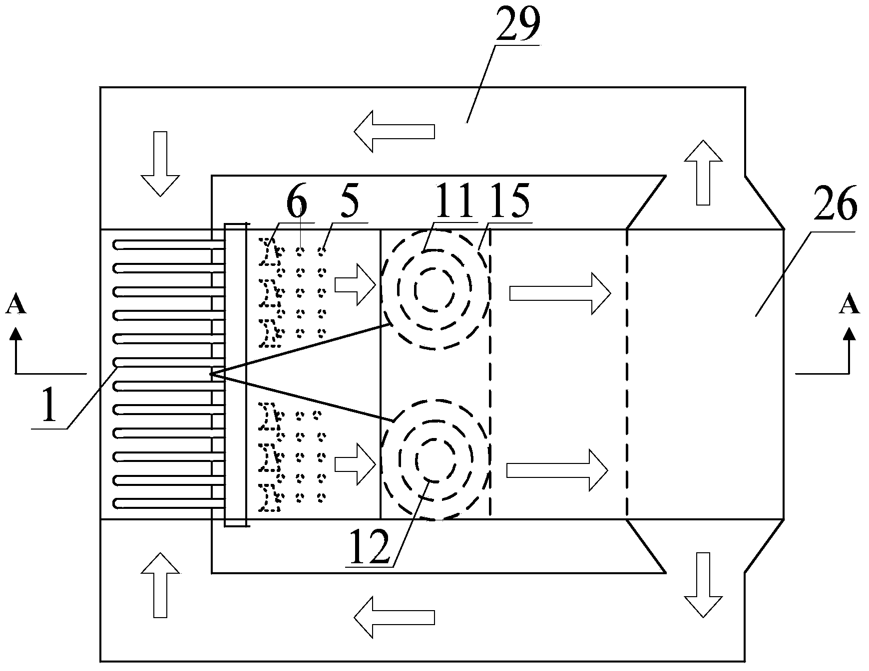
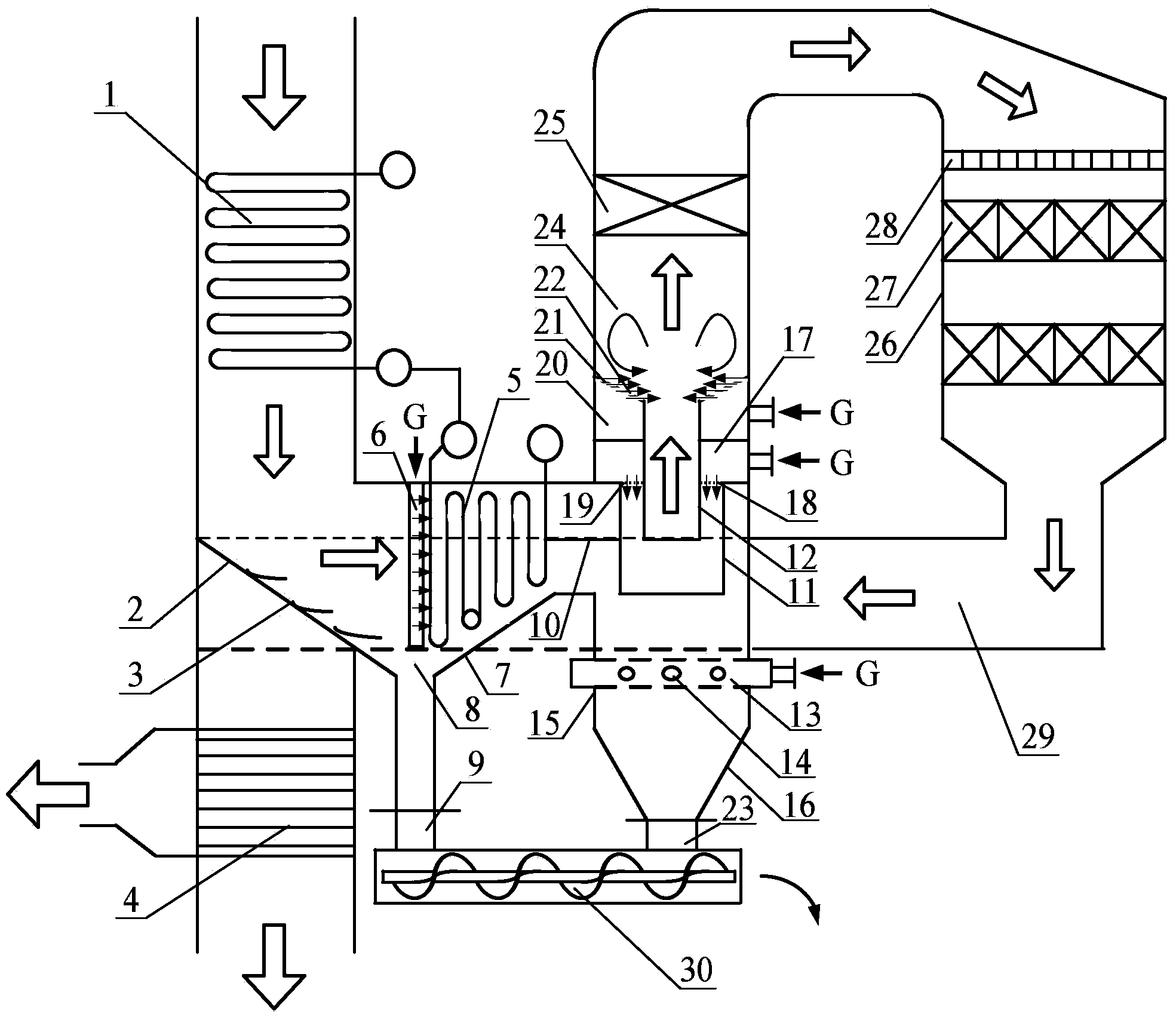
[0006] Purpose of the invention: The present invention aims at the installation of SCR denitrification devices in small and medium-sized boilers, where the vertical flue at the tail of the boiler is compact and there is no sufficient space to pull out and introduce the denitrification flue, and the low and narrow flue has no sufficient space and sufficient time to mix ammonia and flue gas, conventional In the denitrification device, due to the high concentration of fly ash in the flue gas, the catalyst is seriously worn out, etc., and a SCR denitrification device and denitrification method suitable for small and medium-sized boilers are provided.

Method used


Image

  • SCR denitration device and denitration method applicable to middle and small-size boilers
  • SCR denitration device and denitration method applicable to middle and small-size boilers
  • SCR denitration device and denitration method applicable to middle and small-size boilers

Examples


Embodiment Construction

[0031] The implementation of the present invention will be described in detail below with reference to the accompanying drawings. This embodiment is carried out on the premise of this technical solution, and the detailed implementation and operation process are given, but the protection scope of the present invention is not limited to the following embodiments.

[0032] In this example, SCR denitrification technology transformation is carried out for a 170t / h power station coal-fired boiler. When the boiler is operating under rated conditions, the flue gas temperature after the high-temperature economizer in the tail flue is 385°C, and the NOx content is as high as 650mg / Nm 3 , dust content up to 3580mg / Nm 3 , The tail heating surface is arranged in a compact structure, and the distance between the economizer and the air preheater is only 1.2m. According to the characteristics of the flue gas parameters and the original structural characteristics of the boiler, this embodimen...


PUM

PropertyMeasurementUnit
porosityaaaaaaaaaa
porosityaaaaaaaaaa

Abstract

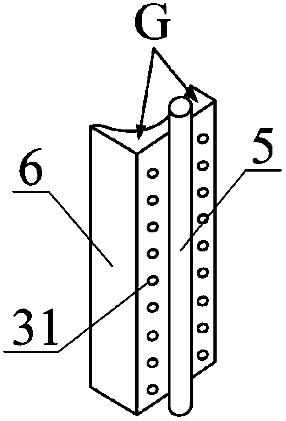
The invention discloses a SCR (Selective Catalytic Reduction) denitration device and a denitration method applicable to middle and small-size boilers. Through structural transformation of an economizer inside a vertical flue, a part of a heated surface is preserved, the other part of the heated surface is moved to a horizontal section of the flue, the rest flue is partitioned in an inclined manner so as to be used for elicitation and introduction of the denitration device; a two-stages dedusting ammonia injection system is arranged so as to mix fume with ammonia, the mixture passes through a catalyst preserved layer and enters a SCR reactor for catalysis reaction, most part of NOx is transformed into N2, the fume after denitration is elicited out from two sides of the lower part of the reactor, enters the flue from two sides of a side wall of the flue at the tail part, and is finally discharged outside the flue through an air pre-heater. The SCR denitration device meets the requirement on the space where the denitration flue needs to be pulled out and led in when the SCR denitration device is additionally arranged on the middle and small-size boilers, sufficient, rapid and effective mixing of ammonia and fume inside a low narrow flue is achieved, and the SCR denitration device has the advantages that the denitration system is compact in structure, high in efficiency, low in catalyst abrasion, and the like.

Description

technical field [0001] The invention relates to an SCR denitrification device suitable for small and medium-sized boilers, and belongs to the technical field of air pollutant control of coal-fired boilers. Background technique [0002] Selective catalytic reduction denitrification technology (SCR technology) refers to the use of reducing agents (such as NH 3 , liquid ammonia, urea) to "selectively" react with NOx in the flue gas and generate non-toxic and pollution-free N 2 and H 2 O. This technology has the characteristics of high NOx removal efficiency, less secondary pollution, and relatively mature technology. It is currently the most widely used and most effective flue gas denitrification technology in the world. How to arrange ammonia injection equipment to effectively mix ammonia and flue gas is the key to improving the denitrification efficiency of SCR denitrification technology. Therefore, for large-scale boilers and small and medium-sized boilers, due to the ob...

Claims


Application Information

Patent Timeline
Patent Type & Authority Applications(China)
IPC IPC(8): B01D53/86B01D53/79B01D53/56B01D50/00
Inventor 张勇金保昇钟文琪
Owner SOUTHEAST UNIV
Learn More