
Air cooling device used for textile printing and dyeing industry

A technology of textile printing and dyeing and air cooling, which is used in textile and papermaking, textile processing machine accessories, and textile material processing, etc. effect, reduce production costs and improve product quality

Inactive Publication Date: 2014-01-15
扬州市江都印染机械有限公司
View PDF0 Cites 3 Cited by
  • Summary
  • Abstract
  • Description
  • Claims
  • Application Information

AI Technical Summary

Problems solved by technology

[0004] 1. The cooling effect is poor. After the continuous running high-temperature fabric contacts and exchanges heat with the surface of the cold water roll body, a large amount of heat energy is accumulated in the metal of the roll body and is guided away without timely heat exchange with the cooling water in the inner cavity of the roll body, resulting in The temperature of the surface of the roller body continues to rise, making the cooling effect worse
[0005] 2. The cooling cost is high. Since a large amount of tap water or ground water must be continuously passed through each chiller, the water consumption is large. In today's increasingly tense water resources, the price of industrial water continues to rise, resulting in rising cooling costs, especially in the absence of The water area uses this method for cooling, and the contradiction is more prominent
[0006] 3. It is not friendly to the environment. In order to reduce costs, some enterprises extract a large amount of groundwater as a cooling medium, causing damage to the groundwater environment
[0007] 4. Increase the amount of pollution control. Many printing and dyeing enterprises that have not realized the separation and discharge of clear and turbid wastewater discharge clean cooling water directly into the sewage ditch, which increases the amount of sewage treatment of the enterprise and increases the cost of pollution control
[0008] 5. The cooling feel is poor. Because the contact cooling method is adopted, the surface of the cooled fabric is easy to harden, lacking a fluffy feel, and not suitable for the cooling process requirements of high-grade fabrics.

Method used


Image

  • Air cooling device used for textile printing and dyeing industry
  • Air cooling device used for textile printing and dyeing industry
  • Air cooling device used for textile printing and dyeing industry

Examples


Embodiment Construction

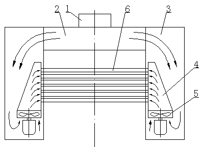
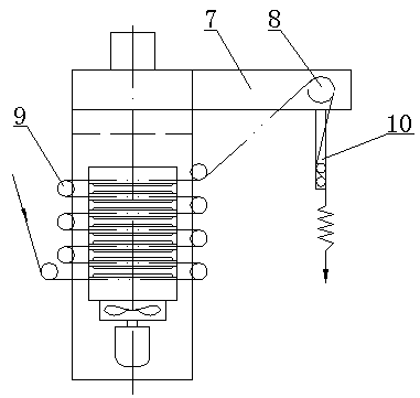
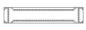
[0016] An air cooling device for the textile printing and dyeing industry, comprising a refrigeration air conditioner 1, a cold air box 2, a box body 3, a tapered air duct 4, an axial flow fan 5, a blowing air box 6, a cloth output frame 7, and a cloth output traction roller 8 , cloth guide roller 9, swinging cloth outlet device 10, a box body 3 is arranged on both sides of the cold air box 2 equipped with a refrigeration air conditioner 1, the inner cavity of the cold air box 2 communicates with the inner cavity of the box body 3, and an axial flow fan 5 is installed at the lower end The tapered air duct 4 is installed in the box body 3, and several blowing air boxes 6 are arranged up and down through the inner panel of the box body 3 to connect with the tapered air duct 4, and a fabric channel is formed between two adjacent blowing air boxes 6 A number of cloth guide rollers 9 are installed alternately on the front and rear sides of the box body 3 and can make the fabric live...


PUM


Abstract

The invention relates to an air cooling device used for the textile printing and dyeing industry. The air cooling device used for the textile printing and dyeing industry comprises a refrigeration air conditioner, a packaged air conditioner, tanks, tapered air hoses, axial fans, air blowing boxes, a cloth draw-out machine frame, a cloth draw-out pull roller, cloth guide rollers and a swinging cloth draw-out device, wherein the tanks are arranged on the two sides of the packaged air conditioner provided with the refrigeration air conditioner, an inner cavity of the packaged air conditioner is communicated with inner cavities of the tanks, the tapered air hoses of which the lower ends are provided with the axial fans are installed inside the tanks, the air blowing boxes are arranged in an up-and-down mode, penetrate through panels on the inner sides of the tanks and are connected and communicated with the tapered air hoses, a fabric channel is formed between two adjacent air blowing boxes, the cloth guide rollers are installed on the front face and the back face of each tank in a staggered mode and can enable fabric to be located in the middle of the fabric channel, the cloth draw-out machine frame is installed at the front end of the packaged air conditioner, the cloth draw-out pull roller is installed at the front end of the cloth draw-out machine frame, and the swinging cloth draw-out device is installed at the lower end of the cloth draw-out pull roller. The air cooling device used for the textile printing and dyeing industry is simple in structure and good in cooling effect; as the front face and the rear face of the fabric are cooled in a penetrating mode, cooling is even, and the hand feeling of the fabric is fluffy.

Description

technical field [0001] The invention relates to an air cooling device for textile printing and dyeing industry. Background technique [0002] In the textile printing and dyeing industry, all kinds of open-width fabrics are dyed, printed, coated, shaped and other finishing processes are carried out under high-temperature conditions, and before the fabrics are stacked in open width or rolled, the fabric All need to be fully cooled to prevent dyes, auxiliaries, etc. from being deteriorated due to oxidation-reduction reactions in contact with air at high temperatures. Therefore, the cooling device is an important general-purpose device widely used in the textile printing and dyeing industry. [0003] At present, the chilled roll cooling method using cooling water as the medium is widely used, that is, tap water or groundwater is continuously poured into one shaft end of the hollow large-diameter roll body, the high-temperature fabric is wrapped around the outer surface of the ro...

Claims


Application Information

Patent Timeline
Patent Type & Authority Applications(China)
IPC IPC(8): D06B5/08D06B23/00
Inventor 谭永贵
Owner 扬州市江都印染机械有限公司
Learn More