U-shaped heat pipe heat exchange element and u-shaped heat pipe heat exchanger integrated with electrostatic precipitator

A technology of electrostatic precipitator and heat pipe heat exchanger, which is applied to indirect heat exchangers, lighting and heating equipment, etc., can solve the problems that direct heat pipes can only be applied, long production cycle, and only suitable for small heat exchangers, etc., to avoid The effect of unplanned forced shutdown, reduced sealing welding workload, and obvious heat transfer safety

Active Publication Date: 2015-11-25
QINGDAO DANENG ENVIRONMENTAL PROTECTION INC
View PDF4 Cites 0 Cited by
  • Summary
  • Abstract
  • Description
  • Claims
  • Application Information

AI Technical Summary

Problems solved by technology

[0005] However, in long-term use, the heat pipe is generally a straight pipe structure, and the working liquid is filled in the straight pipe, which requires sealing and welding at both ends; the heat pipe with the straight pipe structure has a fixed heat transfer limit of the working fluid in the pipe, and cannot adapt to the temperature change condition; The structure of the heat pipe is in the state of a cantilever beam in the heat exchanger, and its rigidity is small. It is only suitable for small heat exchangers and is not suitable for the heat exchanger structure of large-scale equipment such as thermal power plants and petrochemical industries; at the same time, the heat pipe with a single straight pipe structure , both ends of the heat exchanger need to be sealed and welded. When the heat exchanger tube bundle is dense, the welding workload will increase exponentially, and the production cycle will be long, which limits the design and manufacture of large heat pipe heat exchangers. For a long time, straight heat pipes can only be used for small The size of the heat exchanger and the enlargement of the heat pipe heat exchanger are greatly limited

Method used


Image

  • U-shaped heat pipe heat exchange element and u-shaped heat pipe heat exchanger integrated with electrostatic precipitator
  • U-shaped heat pipe heat exchange element and u-shaped heat pipe heat exchanger integrated with electrostatic precipitator
  • U-shaped heat pipe heat exchange element and u-shaped heat pipe heat exchanger integrated with electrostatic precipitator

Examples


Embodiment Construction

[0025] The present invention will be described in further detail below in conjunction with the accompanying drawings and specific embodiments.

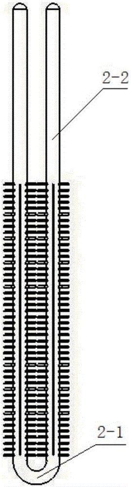
[0026] Such as figure 1 As shown, a U-shaped heat pipe heat exchange element of the present invention is composed of an integrally bent 180° elbow 2-1 and two continuously extending straight sections 2-2. Its extended heating surface adopts H-shaped, spiral, needle-shaped fins, plate-shaped fins or coupling fins.

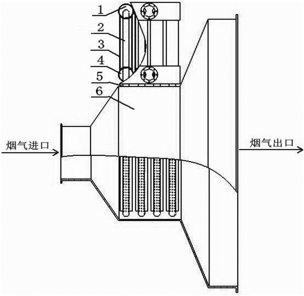
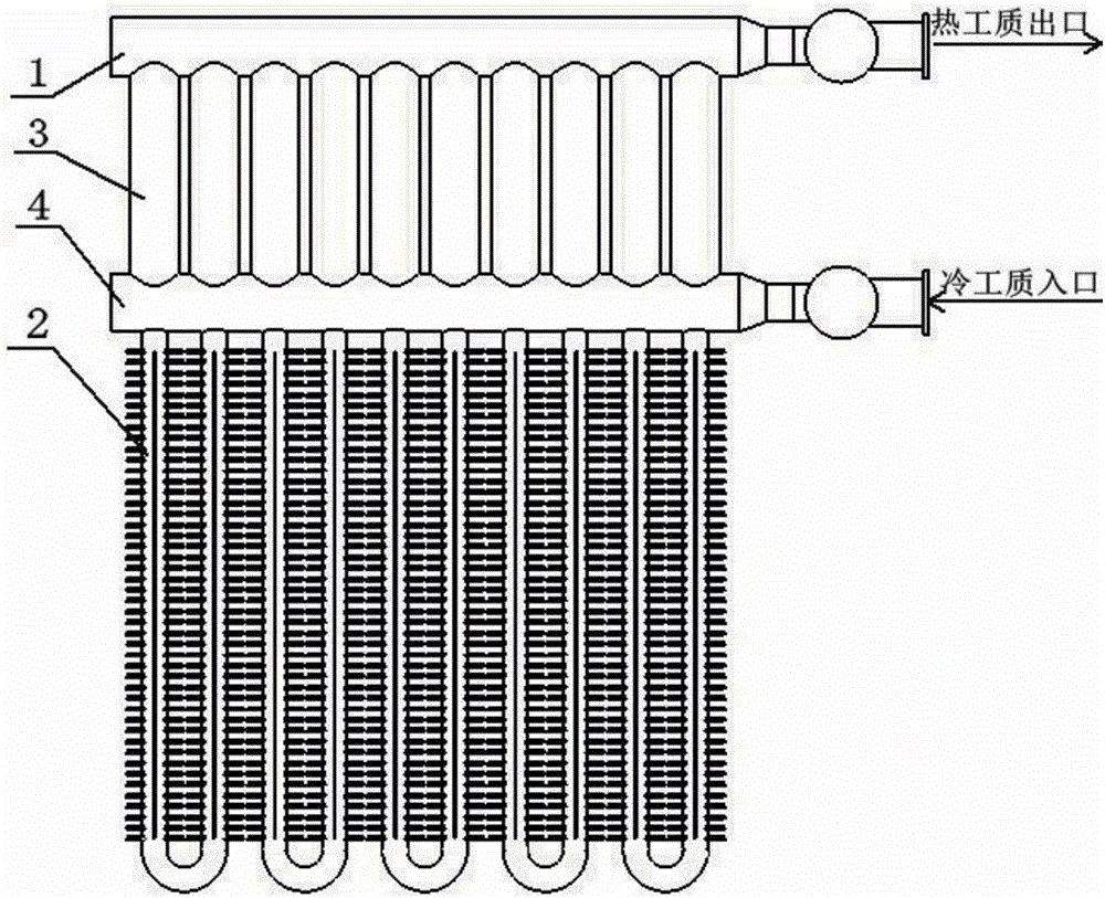
[0027] Such as figure 2 and image 3 As shown, the U-shaped heat pipe heat exchanger integrated with the electrostatic precipitator of the present invention includes a cooling working medium inlet header 4, a thermal working medium outlet header 1, and a cooling working medium inlet header 4 connected to a thermal working medium outlet header. The plurality of cooling medium casing pipes 3 of the box 1 also include the above-mentioned plurality of U-shaped heat pipe heat exchange elements as heat pipes 2, and the upper ...


PUM


Abstract

The invention discloses U-shaped heat pipe heat exchange elements and a U-shaped heat pipe heat exchanger integrated with an electrostatic dust collector. Each U-shaped heat pipe heat exchange element is composed of a 180-degree bend and two continuous-extending straight sections, wherein the bends are formed by whole bending. The U-shaped heat pipe heat exchanger comprises a cooling working medium inlet collecting box, a hot working medium outlet collecting box and a plurality of cooling working medium sleeves communicated with the cooling working medium inlet collecting box and the hot working medium outlet collecting box, and further comprises the U-shaped heat pipe heat exchange elements used as heat pipes. The upper portions of the heat pipes are inserted into the cooling working medium inlet collecting box and inserted into the cooling working medium sleeves. The top ends of the two straight sections of each heat pipe are sealed and inserted into the hot working medium outlet collecting box. The portions, which are not inserted into the cooling working medium inlet collecting box, of the heat pipes are evaporation heat absorption sections. The portions, inserted into the cooling working medium inlet collecting box, of the heat pipes, are condensation heat emission sections. The evaporation heat absorption sections are installed inside the middle of an inlet extension section of the electrostatic dust collector. The condensation heat emission sections are arranged at the upper portion outside a flue in the middle of the inlet extension section of the electrostatic dust collector. The U-shaped heat pipe heat exchange elements and the U-shaped heat pipe heat exchanger are suitable for heat exchanger structures of large-scale equipment in heat-engine plants, the petrochemical industry and the like.

Description

technical field [0001] The invention relates to the technical field of heat pipe heat exchangers, in particular to a U-shaped heat pipe heat exchange element and a U-shaped heat pipe heat exchanger integrated with an electrostatic precipitator. Background technique [0002] When flue gas from boilers and industrial processes flows through the heating surface, its heat distribution is limited to a certain extent, resulting in high flue gas temperatures at the outlet of the air preheater and the inlet of the dust collector. In order to make full use of the heat in the flue gas, It can be realized by setting a waste heat recovery device in the flue gas channel before the bell mouth of the inlet section of the dust collector. However, in some cases, due to the limited space, the arrangement of the flue is extremely compact, and there is no straight section of the flue between the air preheater and the bell mouth of the dust collector inlet section to arrange the waste heat recov...

Claims


Application Information

Patent Timeline
Patent Type & Authority Patents(China)
IPC IPC(8): F28D15/02
Inventor 赵钦新陈中亚陈衡梁志远王云刚
Owner QINGDAO DANENG ENVIRONMENTAL PROTECTION INC
Why Eureka
Try Eureka