Nonsmooth surface fluid friction resistance testing device and nonsmooth surface anti-drag effect evaluating method

A non-smooth surface and fluid friction technology, applied in the direction of measuring devices, mechanical devices, instruments, etc., can solve the problems of difficult operation, high cost, high noise, etc., and achieve the effect of simple and intuitive method, easy operation and reliable results

Inactive Publication Date: 2014-01-15
HARBIN ENG UNIV
View PDF5 Cites 13 Cited by
  • Summary
  • Abstract
  • Description
  • Claims
  • Application Information

AI Technical Summary

Problems solved by technology

The bionic jet surface can reduce the frictional resistance between fluid and solid, and the drag reduction effect is obvious. It is a brand-new drag reduction technology. The current research on this technology is mainly concentrated in the theoretical analysis and numerical simulation stage, because A complete set of test equipment for jet surface testing, so the model test cannot be completed
Most of the traditional drag reduction test studies are carried out in water tunnels, tanks or ponds. However, due to its high cost, huge cost, bulky size, difficult daily maintenance, high noise, uncontrollable test conditions, and complex test models, in All aspects of the test conditions have certain limitations, and none of the above-mentioned devices can be used for the research of the jet surface drag reduction test. especially important
[0003] At present, the drag reduction test devices for non-smooth surfaces and jet surfaces are mostly focused on the rotating jet test method, such as the application number: 201110089369.0, the name is "test device for evaluating the drag reduction effect of bionic non-smooth surface and bionic jet surface" and the application number For: 201120070969.8, the patent application titled "A Test Device for Testing Frictional Resistance". When measuring the frictional resistance of non-smooth surface structures and surface coating structures, it is necessary to process pits, convex hulls, and V on the surface of the cylinder. Type groove and coating, etc., the operation is more difficult

Method used


Image

  • Nonsmooth surface fluid friction resistance testing device and nonsmooth surface anti-drag effect evaluating method

Examples


Embodiment Construction

[0018] The present invention is described in more detail below in conjunction with accompanying drawing example:

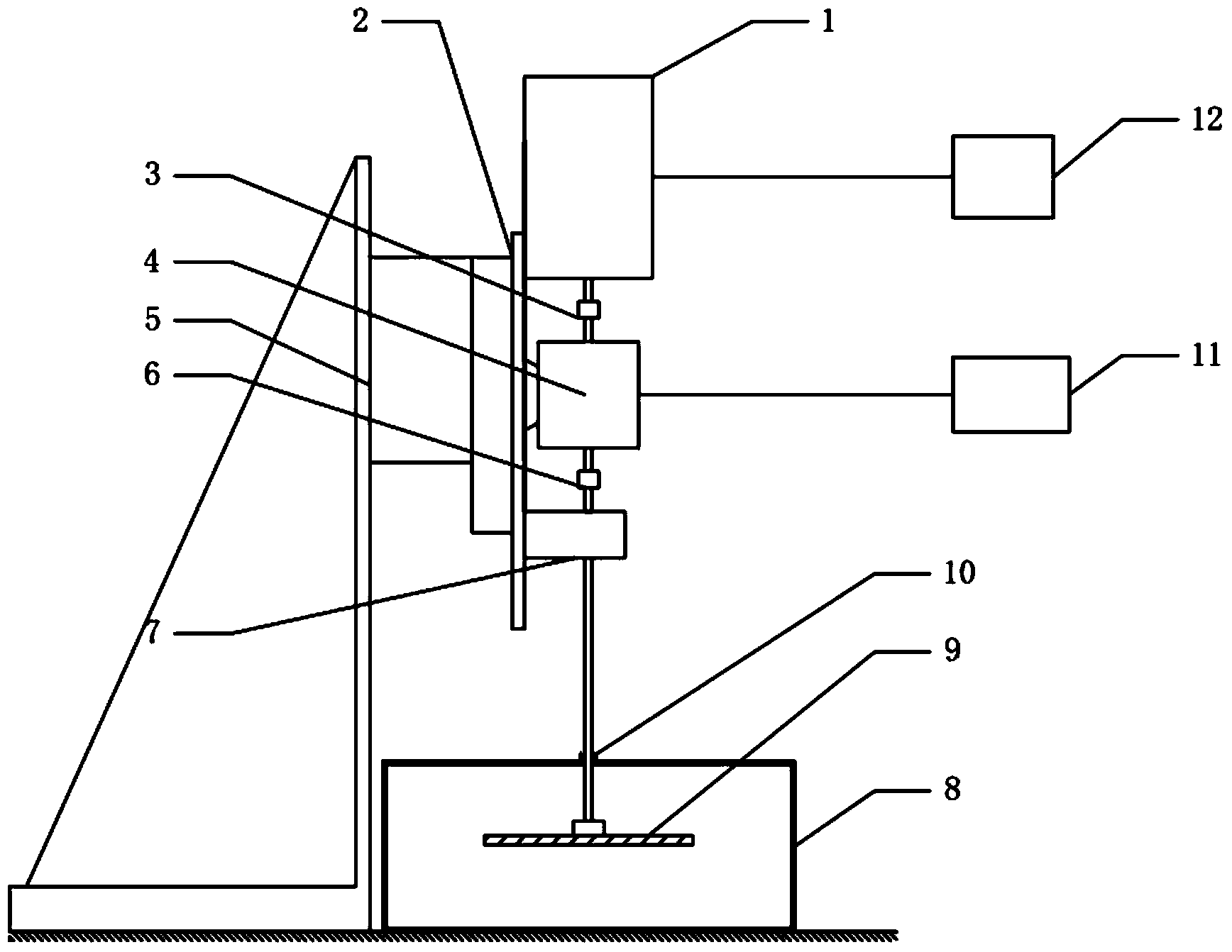
[0019] to combine figure 1 , the non-smooth surface fluid friction resistance testing device of the present invention consists of a stepping motor 1, a guide rail 2, an elastic diaphragm coupling 3, a torque signal coupler 4, a support table 5, an airtight water tank 8, a rotating disc 9, a computer 11, It consists of 12 servo hybrid stepper motor drivers. Both the stepper motor 1 and the torque signal coupler 4 are fixed on the guide rail 2 , and the guide rail 2 is installed on the supporting platform 5 . The stepping motor 1 is controlled by a servo hybrid stepping motor driver 12, the stepping motor 1 drives the torque signal coupler 4 through the elastic diaphragm coupling 3, and the torque signal coupler 4 drives the rotation through the elastic diaphragm coupling 6 Disc 9 movement.

[0020] The torque signal coupler 4 transmits the collected torque, powe...


PUM

PropertyMeasurementUnit
transmittivityaaaaaaaaaa

Abstract

The invention aims to provide a nonsmooth surface fluid friction resistance testing device and a nonsmooth surface anti-drag effect evaluating method. The device comprises a stepper motor, a torque signal coupler, a rotating shaft and a water tank, wherein the stepper motor is connected with the torque signal coupler through a first flexible diaphragm coupling; an output shaft of the torque signal coupler is connected with the rotating shaft through a second flexible diaphragm coupling; a rotating disc is mounted at the end of the rotating shaft, arranged in the closed water tank, and driven by the stepper motor to rotate; the torque signal coupler acquires torque, power and rotating speed signals of the rotating disc, and transmits into a computer; the stepper motor and the torque signal coupler are both fixed on a guide rail; the guide rail is mounted on a supporting table; the rotating shaft is parallel to the guide rail. The device adopts the structure of the rotating disc, so that the processing of the nonsmooth surface structure on the surface of the disc or the implementing of the surface coating is easier and more convenient, and the dismantling of the rotating disc is simpler.

Description

technical field [0001] The invention relates to a testing device for the frictional resistance of a fluid to a solid surface structure and a method for evaluating the drag reduction effect on a non-smooth surface and a surface coating structure. Background technique [0002] At present, relevant scholars at home and abroad have carried out extensive and in-depth theoretical exploration and applied research on the problem of motion drag reduction between fluid and solid interfaces, and have successfully achieved remarkable progress in many aspects. Since the problem of drag reduction can directly affect the energy consumption and mechanical properties of equipment, the research on this problem has always been concerned by experts and scholars from various countries. The research methods are mainly from theoretical analysis, numerical simulation, model test and other aspects. The drag reduction performance of the sample is tested in the test device and the required conclusions...

Claims


Application Information

Patent Timeline
Patent Type & Authority Applications(China)
IPC IPC(8): G01N19/02
Inventor 赵刚李芳刘维新杜军伟臧东阳孙壮志张殊刘明明李照远
Owner HARBIN ENG UNIV
Why Eureka
Try Eureka