
Time-to-digital converter

A technology of time-to-digital converters, which is applied in the field of high-precision and large-range time-to-digital converters, can solve the problems of large chip area overhead, achieve small area overhead, and achieve the effect of high-precision and large-scale time interval measurement

Active Publication Date: 2014-01-15
INST OF ELECTRONICS CHINESE ACAD OF SCI
View PDF5 Cites 20 Cited by
  • Summary
  • Abstract
  • Description
  • Claims
  • Application Information

AI Technical Summary

Problems solved by technology

[0004] In order to solve the technical problem that the cost of chip area in the prior art is larger than that of TDL, the purpose of the present invention is to provide a time-to-digital converter with high precision, large input range and small chip area to solve the problems encountered in current time measurement. main problem

Method used


Image

  • Time-to-digital converter
  • Time-to-digital converter
  • Time-to-digital converter

Examples


Embodiment Construction

[0040] In order to make the objectives, technical solutions, and advantages of the present invention clearer, the following further describes the present invention in detail with reference to specific embodiments and drawings.

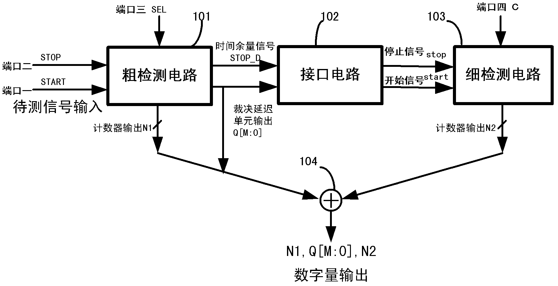
[0041] Such as figure 1 As shown, the time-to-digital converter described in the present invention includes a coarse detection circuit 101, an interface circuit 102, a fine detection circuit 103, and a calculation unit 104.

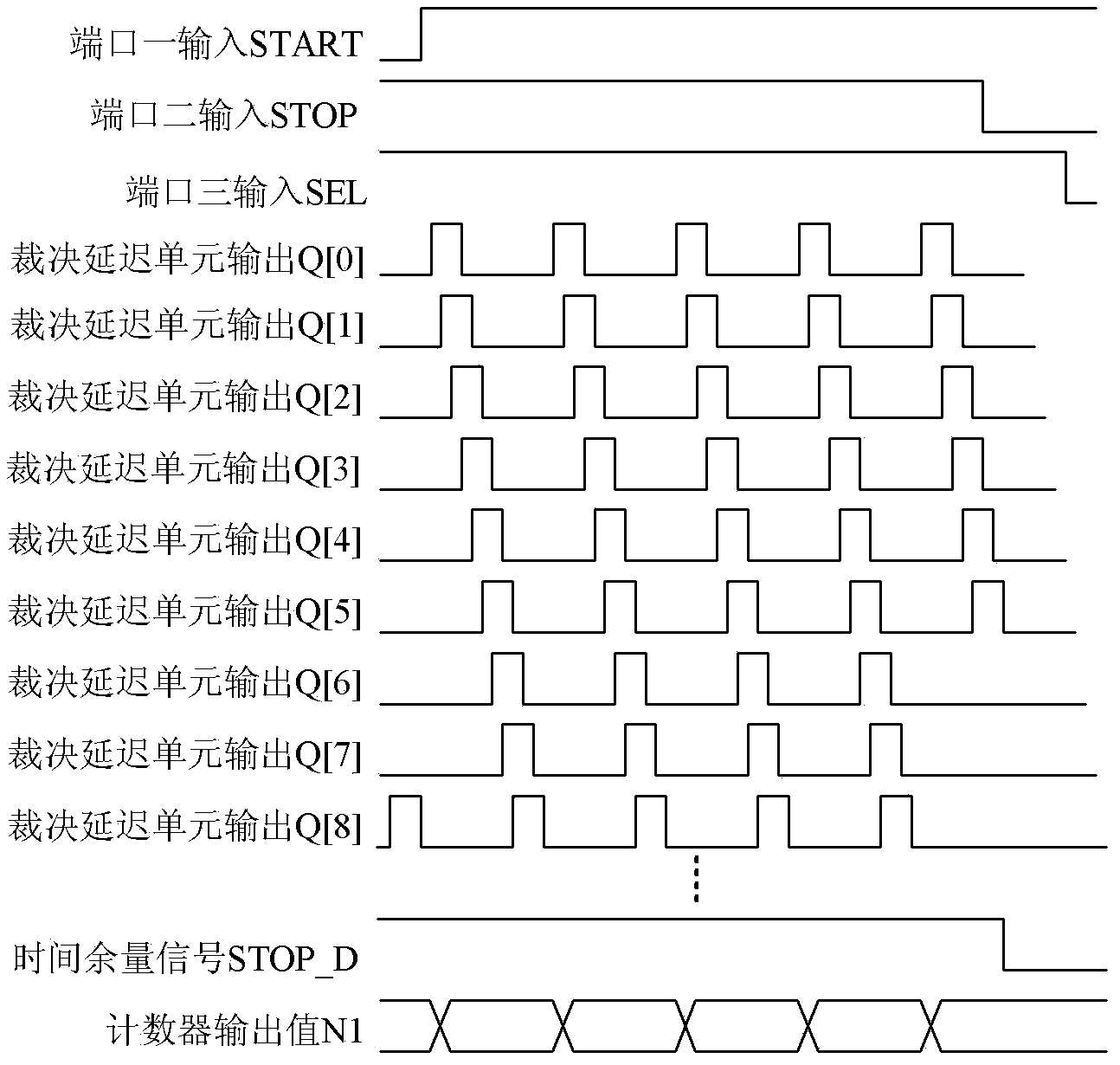
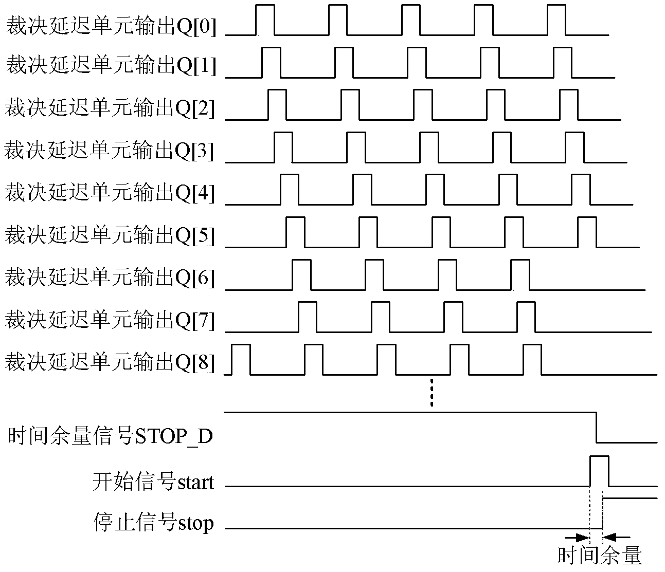
[0042] A rough detection circuit 101 has port 1, port 2 and port 3. Among them: port 3 receives the input level signal and is used to select different measurement ranges for different level signals; port 1 and port 2 are used to receive respectively Input two transition edge signals with continuous time intervals, and use the loop delay line in the coarse detection circuit 101 to roughly measure the time interval between the two transition edge signals with continuous time intervals, and perform a rough measurement on the port Count th...


PUM


Abstract

The present invention provides a time-to-digital converter which comprises the following components: a coarse detecting circuit, an interface circuit and a fine detecting circuit, wherein the coarse detecting circuit finally realizes time-to-digital convection in a large input range by means of counter through designing a delay line to an annular member and multiplexing a judging unit as a delaying unit. The interface circuit is used for transmitting a time allowance which is generated by the coarse detecting circuit to the fine detecting circuit. The fine detecting circuit realizes high-precision time-to-digital convection with adjustable precision through adjusting a gate oxide capacitor of a field effect transistor and fixing the frequency difference between two oscillators in a differential annular oscillator to a fixed small value. Overall, through the three modules, the time-to-digital converter of the invention can perform high-precision large-range convection on the time interval through a relatively small area expenditure.

Description

Technical field [0001] The invention belongs to the technical field of time measurement, and relates to a high-precision large-range time-to-digital converter. Background technique [0002] As a key technology, high-precision and large-scale time measurement is widely used in many fields, such as laser ranging (LRF), navigation and communication, high-energy physics experiments, satellite monitoring, scientific metrology and other fields. Precise time measurement is indispensable in both national defense and civilian fields. With the development of technology, time measurement is developing in the direction of high precision and large input range to meet the requirements of many applications. [0003] Time-to-Digital Converter (TDC) is a device that converts time interval into digital output. It is similar to Analog-to-Digital Converter (ADC) to a certain extent, except ADC quantifies voltage or current, while TDC quantifies time interval. So far, the typical methods of TDC can b...

Claims


Application Information

Patent Timeline
Patent Type & Authority Applications(China)
IPC IPC(8): H03M1/50
Inventor 王新刚杨海钢
Owner INST OF ELECTRONICS CHINESE ACAD OF SCI
Learn More