Laser drilling device assisted by laser-induced impact waves

A laser-induced and assisted laser technology, applied in laser welding equipment, welding equipment, metal processing equipment, etc., can solve problems such as micro-cracks in holes, and achieve the effects of avoiding retention, increasing speed, and reducing thickness

Active Publication Date: 2014-01-22
盐城市奇镌激光科技有限公司
View PDF6 Cites 13 Cited by
  • Summary
  • Abstract
  • Description
  • Claims
  • Application Information

AI Technical Summary

Problems solved by technology

[0007] 2. A recast layer with a certain thickness attached to the hole wall will cause micro-cracks in the hole. The thicker the recast layer

Method used


Image

  • Laser drilling device assisted by laser-induced impact waves

Examples


Embodiment Construction

[0028] In order to better illustrate the implementation details of the present invention, the technical solutions of the present invention will be further described below in conjunction with the accompanying drawings.

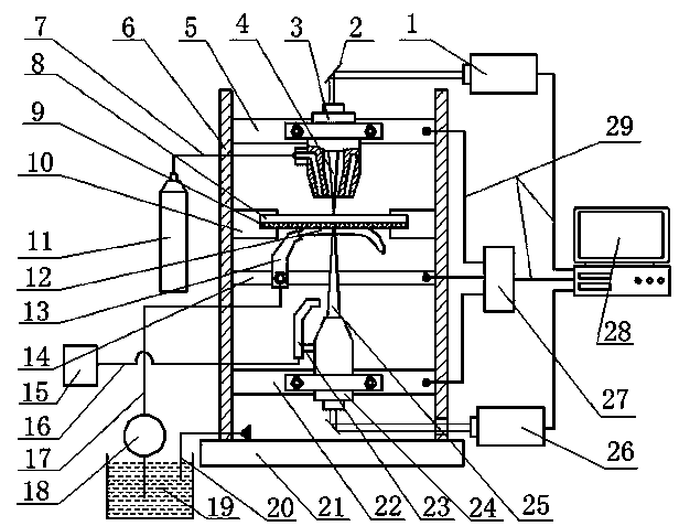
[0029] Such as figure 1 As shown, the device for laser-induced shock wave-assisted laser drilling of the present invention includes: workpiece clamping device, laser drilling device, laser-induced shock wave device, control system device; laser drilling device and laser-induced shock wave device from top to bottom They are respectively installed on the workpiece clamping device, and the control system device is respectively connected with the laser drilling device and the laser induced shock wave device through the cable 29;

[0030] Described workpiece clamping device comprises base 21, frame 6, clamp 10, wherein, frame 6 is fixed on the base 21, and clamp 10 is installed on frame 6 middle position, is coated with the workpiece 8 clamping of absorbing...


PUM

PropertyMeasurementUnit
thicknessaaaaaaaaaa
thicknessaaaaaaaaaa

Abstract

The invention discloses a laser drilling device assisted by laser-induced impact waves. The laser drilling device comprises four modules, namely, a workpiece clamping device, a laser drilling device, a device capable of allowing a laser to induce the impact waves and a control system device, wherein the laser drilling device and the device capable of allowing the laser to induce the impact waves are arranged on the workpiece clamping device from top to bottom, and the control system device is connected with the laser drilling device and the device capable of allowing the laser to induce the impact waves through cables. According to the laser drilling device assisted by the laser-induced impact waves, the depth limit of laser drilling can be improved, the thickness of a recast layer can be lowered, the micro-crack producing rate can be lowered, the laser drilling efficiency can be improved, and the laser drilling device can be applied to laser drilling of medium plates and thick plates.

Description

technical field [0001] The invention relates to the technical field of laser processing, in particular to a device that utilizes laser-induced shock waves to assist laser drilling. technical background [0002] Laser drilling technology is one of the earliest application technologies of laser in the field of material processing. During the laser drilling process, the high-energy pulsed laser is focused on the surface of the workpiece to heat, melt or even vaporize the material, and then the molten material is extruded out of the hole under the joint action of the recoil pressure of the rapid expansion of the metal vapor and the pressure of the high-pressure auxiliary gas. , the subsequent pulsed laser continues the above process, and the material is continuously removed until a blind hole or a through hole is formed. [0003] Compared with other drilling methods, laser drilling has significant advantages such as large hole depth-to-diameter ratio, no contact, no tool loss,...

Claims


Application Information

Patent Timeline
Patent Type & Authority Applications(China)
IPC IPC(8): B23K28/02B23K26/382B23K26/70
CPCB23K26/142B23K26/146B23K26/18B23K26/356B23K26/382
Inventor 戴峰泽温德平张永康
Owner 盐城市奇镌激光科技有限公司
Why Eureka
Try Eureka