Check patentability & draft patents in minutes with Patsnap Eureka AI!

A thermionic device and its manufacturing method

A thermionic and device technology, applied in electric solid state devices, semiconductor devices, semiconductor/solid state device components, etc., can solve the problems of limiting photovoltaic and thermoelectric conversion efficiency, high product cost, and poor thermal insulation, etc. Simple structure, lower production cost, stable and reliable performance

Active Publication Date: 2015-09-30
苏州图卡节能科技有限公司
View PDF9 Cites 0 Cited by
  • Summary
  • Abstract
  • Description
  • Claims
  • Application Information

AI Technical Summary

Problems solved by technology

In the process of these conversions, there are conversion losses, low power generation efficiency and bulky
Solar photovoltaic system or thermosemiconductor power generation is connected by a material with poor thermal insulation and low thickness between the hot end and the cold end, and its heat conduction loss limits the electrical conversion efficiency of photovoltaics and thermosemiconductors
Thermionic power generation technology can directly convert heat into electrical energy, with high theoretical efficiency. It has no moving parts and has a long life. However, the distance between the emitter and receiver electrodes needs to be controlled within 10 nanometers to obtain a good Effect, the traditional processing technology can not meet the gap control requirements
Although U.S. Patent US7169006B2 provides a control method for the gap, its structure and manufacturing process have high product cost

Method used


Image

  • A thermionic device and its manufacturing method
  • A thermionic device and its manufacturing method

Examples


Embodiment Construction

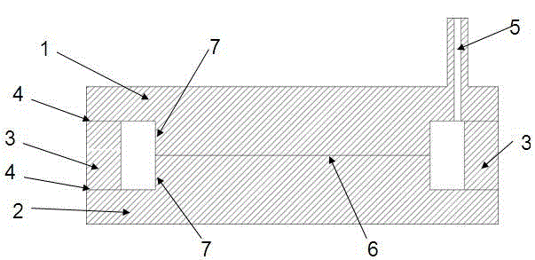
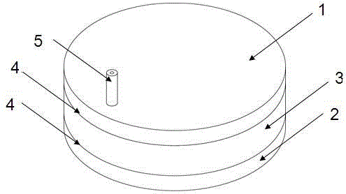
[0015] The present invention is described in detail below in conjunction with accompanying drawing and specific embodiment: as figure 1 with figure 2 As shown, 1 is the thermion emitter plate, 2 is the thermion receiving plate, 3 is the control ring, 4 is the thermal insulation sealing layer, 5 is the process hole; 6, the gap; 7, the protruding part.

[0016] In this embodiment, the thermionic emitter plate 1 and thermionic receive plate 2 are made of red copper, the control ring is made of an aluminum alloy ring material, and the thermal insulation sealing layer is made of epoxy resin sealing material as an example to explain the thermionic device. How to make and use it. First put the aluminum alloy control ring 3 in the middle of thermion emitter plate 1 and thermion receiver plate 2, the thickness of the aluminum alloy control ring 3 is slightly smaller than the protruding part of thermion emitter plate 1 and thermion receiver plate 2 The sum of the heights of 7, the he...


PUM


Abstract

The invention relates to a novel thermionic device. The device comprises an emitting electrode plate, a receiving electrode plate and a control ring, wherein the emitting electrode plate is used for emitting thermal ions; the receiving electrode plate is used for capturing the thermal ions; the control ring is used for controlling a gap between the two electrode plates and is connected with the two electrode plates through heat-insulation insulating layers; the spacing gap between the two electrode plates is controlled within 0.1-100 nanometers by the aid of the thermal expansion property of the control ring; and a closed vacuum chamber is formed among the two electrode plates, the heat-insulation insulating layers and the control ring. With the adoption of the device, the efficiency of heat energy generation can be greatly improved; in addition, refrigeration can be conducted after the device is electrified, the size is greatly reduced, the refrigeration efficiency can reach or exceed the traditional vapor compression type refrigeration efficiency, so that energy consumption is reduced.

Description

technical field [0001] The invention relates to a thermionic device and a manufacturing method thereof in the application field of thermionic power generation and thermionic refrigeration. Background technique [0002] At present, most of the electric energy in the world is obtained by converting fossil energy and nuclear energy into thermal energy, converting thermal energy into mechanical energy through steam, or directly using the mechanical energy transmitted by the wind wheel or water wheel to push the generator to cut the magnetic force line. In the process of these conversions, there are conversion losses, low power generation efficiency and bulky volume. Solar photovoltaic system or thermosemiconductor power generation is connected by a material with poor thermal insulation and low thickness between the hot end and the cold end, and its heat conduction loss limits the electrical conversion efficiency of photovoltaics and thermosemiconductors. Thermionic power genera...

Claims


Application Information

Patent Timeline
Patent Type & Authority Patents(China)
IPC IPC(8): H01J45/00H01L23/04H01L23/051
Inventor 魏辉
Owner 苏州图卡节能科技有限公司
Features
  • R&D
  • Intellectual Property
  • Life Sciences
  • Materials
  • Tech Scout
  • Unparalleled Data Quality
  • Higher Quality Content
  • 60% Fewer Hallucinations
Learn More