Flexible photoelectric device substrate, flexible photoelectric device and preparation method

A kind of optoelectronic device, flexible technology, applied in the direction of electrical solid device, semiconductor/solid device manufacturing, photovoltaic power generation, etc., can solve the problems of small device mobility, residual glue, alignment difficulties, etc., and achieve the effect of preventing falling off

Active Publication Date: 2014-01-22
TCL CORPORATION
View PDF4 Cites 15 Cited by
  • Summary
  • Abstract
  • Description
  • Claims
  • Application Information

AI Technical Summary

Problems solved by technology

This method has the following disadvantages in the following three aspects: 1. Difficulty in alignment during the production process; 2. There is residual glue after the plastic substrate is separated from the carrier; 3. The engineering temperature of the TFT-array (liquid crystal layer) is limited, which directly leads to TFT (thin film field effect transistor) device mobility is small
[0005] Through the above method, flexible optoelectronic devices can be produced on a production line with a small glass substrate, but due to the large difference in thermal expansion coefficient between the polymer film (>15ppm/°C) and the glass substrate (3ppm/°C), in TFT-array During the manufacturing process, after repeated temperature changes, the polymer film bulges, especially the phenomenon that the polymer film falls off around the substrate
In the process of TFT-array engineering,

Method used


Image

  • Flexible photoelectric device substrate, flexible photoelectric device and preparation method
  • Flexible photoelectric device substrate, flexible photoelectric device and preparation method
  • Flexible photoelectric device substrate, flexible photoelectric device and preparation method

Examples


Example Embodiment

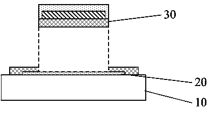
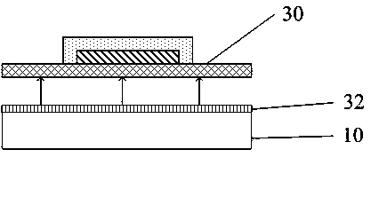
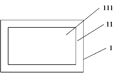
[0031] The present invention provides a flexible optoelectronic device substrate, a flexible optoelectronic device and a preparation method. In order to make the objectives, technical solutions and effects of the present invention clearer and clearer, the present invention will be described in further detail below. It should be understood that the specific embodiments described herein are only used to explain the present invention, but not to limit the present invention.

[0032] In the process of studying the surface characteristics of polymer materials and various metals, the present invention confirms through experiments that some metal materials and polymer films have good adhesion characteristics, and thus proposes a flexible optoelectronic device for making flexible optoelectronic devices. A device substrate and a preparation method thereof. The flexible optoelectronic device substrate is not only suitable for the preparation of large-size flexible optoelectronic devices, bu...


PUM

PropertyMeasurementUnit
Thicknessaaaaaaaaaa

Abstract

The invention discloses a flexible photoelectric device substrate, a flexible photoelectric device and a preparation method. The flexible photoelectric device substrate comprises a glass baseplate and a metal thin film which is used for buffering expansion amount difference between a macromolecule thin film and the glass baseplate so that the macromolecule thin film can be prevented from falling off from the glass baseplate. The metal thin film is arranged on the edge area of the surface of the glass baseplate. The metal thin film is enclosed on the surface of the glass baseplate so that a panel forming area used for processing the flexible photoelectric device is formed. The flexible photoelectric device substrate is used for preparing the flexible photoelectric device. With application of the flexible photoelectric device substrate, the macromolecule thin film can be prevented from falling off from the glass baseplate. The flexible photoelectric device substrate provided by the invention is applicable to preparation of an OLED, OLED lighting, electronic paper display, a touch screen and other non-display technologies.

Description

technical field [0001] The invention relates to the field of preparation of flexible photoelectric devices, in particular to a flexible photoelectric device substrate, a flexible photoelectric device and a preparation method. Background technique [0002] Organic light-emitting devices (hereinafter referred to as OLED) are currently mainly used in the screens of small-sized smartphones below 5 inches, and are currently challenging large-sized screens above 10 inches. So far, the largest OLED screens produced by humans have reached more than 50 inches, such as: Samsung, LG's 55-inch and Sony's, Panasonic's 56-inch OLED TV. However, in the field of large-size display screens, LCD (liquid crystal display) is currently the mainstream product, because LCD is far better than OLED in terms of cost performance, making it difficult for OLED to enter the market. Flexible display is one of the main directions for the differentiation of OLED and LCD products. OLED is an active light-e...

Claims


Application Information

Patent Timeline
IPC IPC(8): H01L51/52H01L51/56
CPCH10K71/80H10K77/111Y02E10/549Y02P70/50
Inventor 申智渊黄宏付东
Owner TCL CORPORATION
Why Eureka
Try Eureka