
Small-sized broadband end-on-fire antenna

An end-fire antenna, broadband technology, applied in the field of small antenna terminals, can solve the problems of narrow operating frequency band, low gain, large antenna size, etc., and achieve the effect of broadband gain, high gain, and increased impedance

Active Publication Date: 2014-01-22
上海航空机械有限公司
View PDF5 Cites 13 Cited by
  • Summary
  • Abstract
  • Description
  • Claims
  • Application Information

AI Technical Summary

Problems solved by technology

The main problem that restricts the application of Yagi antennas in handheld devices is that the size of the antenna is too large, and the narrow working frequency band and low gain caused by the reduction of the antenna size are the main problems that need to be solved

Method used


Image

  • Small-sized broadband end-on-fire antenna
  • Small-sized broadband end-on-fire antenna
  • Small-sized broadband end-on-fire antenna

Examples


Embodiment Construction

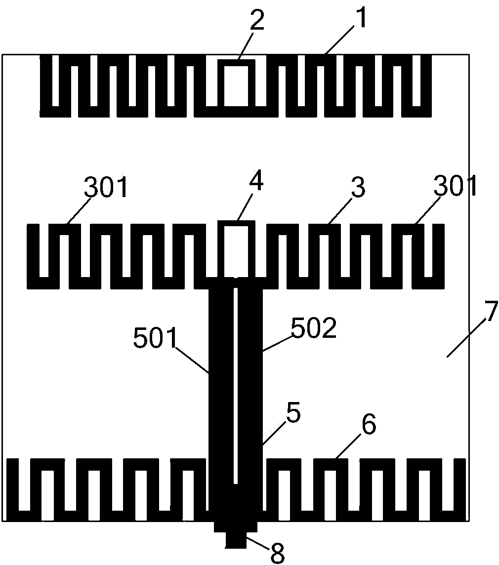
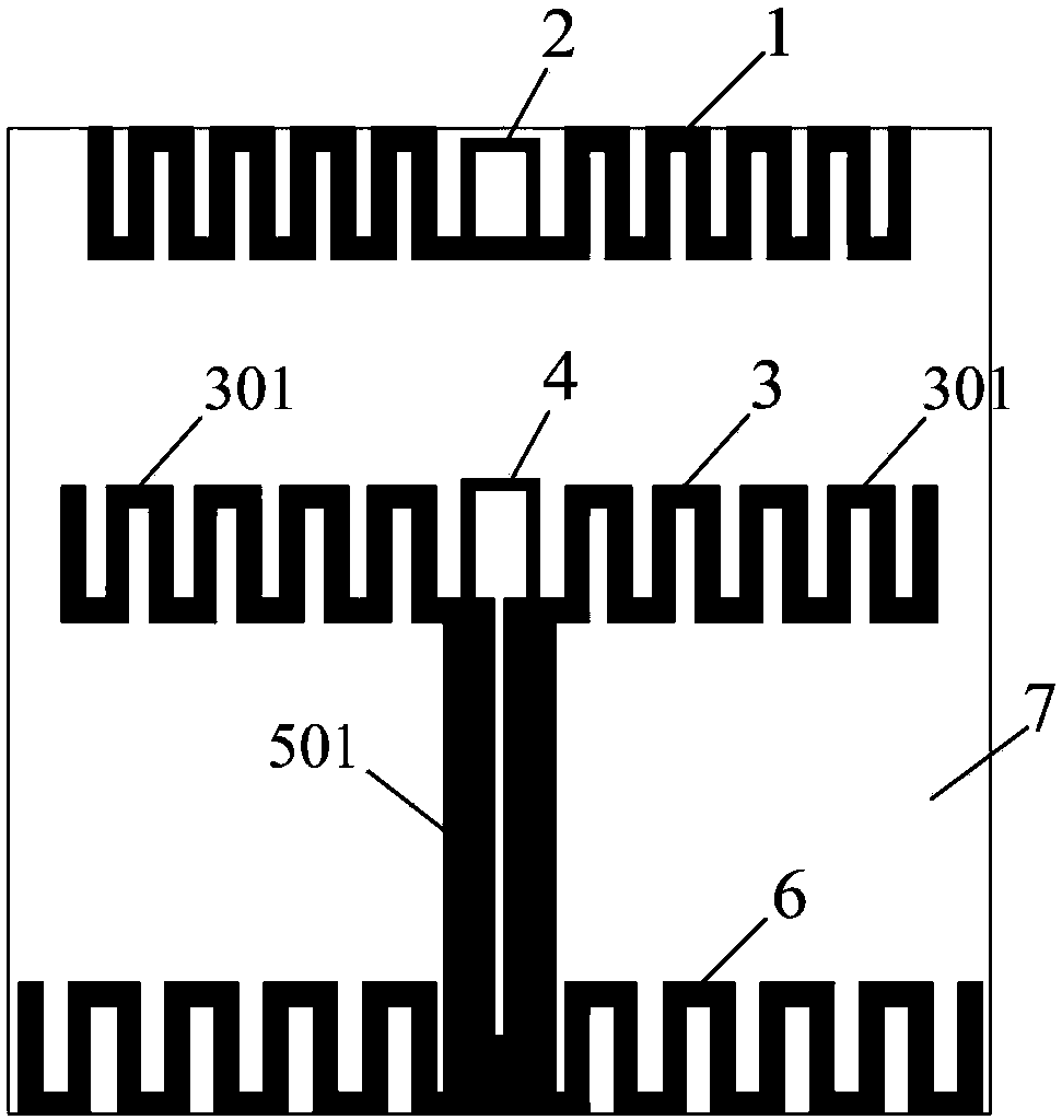
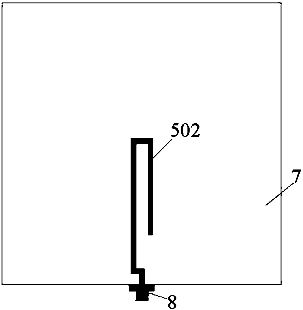
[0032] Please refer to figure 1 , figure 2 and image 3 , the present invention is a small broadband end-fire antenna, which includes a director 1, the director 1 is placed at the front end of the antenna, and has several symmetrical gate-shaped broken line structures. Gain adjuster 2, the two ends of the gain adjuster 2 are connected to the middle of the director 1, which is formed by a bent line segment. The exciter 3, the exciter 3 is placed parallel to the director 1, the exciter 3 includes a two-arm vibrator 301 structure, and the two-arm vibrator 301 is a number of symmetrical gate-shaped broken line structures. The two ends of the tuner 4 are connected to the inner side of the two-arm vibrator 301, which is a bent line segment structure. The feeding balun 5 is an electromagnetically coupled balun with a microstrip structure. The front of the feeding balun 5 is a microstrip parallel double-wire 501 structure, and its upper end is connected to the inner side of the tw...


PUM


Abstract

The invention discloses a small-sized broadband end-on-fire antenna. The small-sized broadband end-on-fire antenna comprises a director, an exciter, a tuner, a feed balun, a reflector, a cable joint and a dielectric substrate, wherein the exciter is arranged opposite to the director in parallel and is of a two-arm vibrator structure; the two ends of the tuner are bridged on the inner side positions of the two-arm vibrator; the feed balun is of a micro-strip line-to-parallel double line structure; two output ends of the parallel double lines are connected with the inner side of the two-arm vibrator of the exciter respectively; the reflector is arranged opposite to the exciter in parallel and is connected with the parallel double lines of the feed balun; the director, the exciter and the reflector are all of bend line structures; the cable joint is connected with the feed balun; the director, a gain adjuster, the exciter, the tuner, the feed balun and the reflector are all arranged on the dielectric substrate. Small size, broad band and high gain of the antenna are simultaneously realized.

Description

technical field [0001] The invention relates to a small broadband end-fire antenna, in particular to a small antenna terminal used as an ultra-high frequency radio frequency identification handset. technical background [0002] Radio frequency identification technology (RFID) is a new automatic identification technology developed in the 1980s, which has been widely used in logistics, management, charging, access control and other occasions. Radio frequency identification technology is to realize non-contact information transmission through the emission and reception of electromagnetic waves, and to identify and classify the transmitted information. The hardware composition of the radio frequency identification system mainly includes two parts: the reader and the label. The tag stores the information of the target object and is attached to the target object. The reader emits electromagnetic waves to irradiate the area where the tag is located. After the tag is irradiated, th...

Claims


Application Information

Patent Timeline
IPC IPC(8): H01Q1/36H01Q19/30H01Q23/00H01Q1/22
Inventor 陈曦张思敏傅光雷娟惠朝辉
Owner 上海航空机械有限公司
Learn More