Garbage leachate treating device

A technology of landfill leachate and treatment device, which is applied in aerobic process treatment, sustainable biological treatment, water/sewage multi-stage treatment, etc., can solve the operation cost of short-term membrane service life, high aeration energy consumption can not reduce process operation Maintenance costs, difficulties in stable operation of new processes, etc., to achieve the effects of reducing the number of membrane cleanings, sensitive control of treatment reaction parameters, and stable operation of treatment processes

Inactive Publication Date: 2014-01-29
NORTH CHINA ELECTRIC POWER UNIV (BAODING)
View PDF5 Cites 14 Cited by
  • Summary
  • Abstract
  • Description
  • Claims
  • Application Information

AI Technical Summary

Problems solved by technology

The new biological denitrification process has obvious advantages over the traditional denitrification process, such as: reducing feeding energy consumption, no need to add carbon sources, saving operating costs, etc. However, the occurrence of the new process requires strict specific conditions, such as higher temperature , appropriate dissolved oxygen, etc., so this also leads to the reason why the new process is difficult to operate stably in actual engineering
[0008] Membrane bioreactor is an advanced landfill leachate treatment technology, with stable treatment effect and can adapt to water quality under different environmental conditions. However, in the application process, an efficient pretreatment process is still required to improve the biodegradability of leachate, high rate Membrane fouling and short membrane service life have led to increased operating costs, and the aeration measures taken to slow down membrane fouling, the high aeration energy consumption still cannot reduce the operation and maintenance costs of the process

Method used


Image

  • Garbage leachate treating device
  • Garbage leachate treating device
  • Garbage leachate treating device

Examples


Embodiment Construction

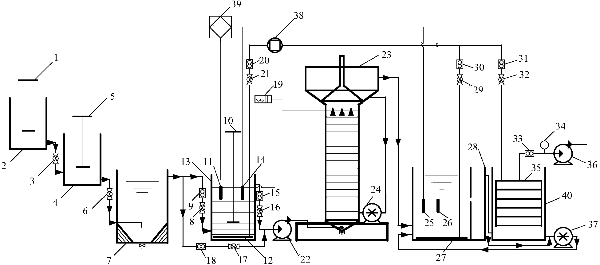
[0033] The present invention provides a landfill leachate treatment device, and the present invention will be further described below in combination with specific embodiments.

[0034]A landfill leachate treatment device, in which the adsorption tank 2 is connected to the coagulation tank 4 through the first electric valve 3, and the coagulation tank 4 is connected to the sedimentation tank 7 through the second electric valve 6; the sedimentation tank 7 The first liquid flow sensor 9 and the third electric valve 8 are connected to the nitrosation reactor 13 successively, and the sedimentation tank 7 is connected to the water inlet pump 22 through the second liquid flow sensor 18 and the fourth electric valve 17 successively; The nitrification reactor 13 is connected to the water inlet pump 22 successively through the third liquid flow sensor 15 and the fifth electric valve 16, and the nitrosation reactor 13 is connected to the temperature controller 19; the temperature controll...


PUM


Abstract

The invention belongs to the technical field of waste water treatment and particularly relates to a garbage leachate treating device. By virtue of the garbage leachate treating device, an adsorption-coagulation-nitrosation-anaerobic ammonium oxidation-aerobic treatment-membrane bioreactor combined process can be applied to the treatment of garbage leachate. The garbage leachate treating device comprises the following three parts: a. a pretreatment part which is formed by means of sequentially connecting an adsorption tank, a coagulation tank and a sedimentation tank; b. a denitrification part which is formed by a nitrosation reactor and an anaerobic ammonium oxidation reactor; and c. a main body treatment part which is formed by an aerobiotic tank and a membrane tank. Aiming at the water quality characteristics of the garbage leachate, the garbage leachate treating device organically combines a physicochemical treatment unit and a biological treatment unit; simultaneously the treating device is transformed reasonably and has the advantages of short and compact technological process, high treatment efficiency, low energy consumption, long membrane-component service life, and the like.

Description

technical field [0001] The invention belongs to the technical field of waste water treatment, in particular to a landfill leachate treatment device. Background technique [0002] At present, the main methods of urban waste disposal are sanitary landfill and incineration. Regardless of whether incineration or sanitary landfill is used, a certain amount of high-concentration organic wastewater will be produced during the disposal process. High-concentration organic wastewater generally refers to the entry of rainwater that exceeds the water holding capacity of the garbage and its covering soil layer and the surface evaporation potential into the landfill site. Finally, the leachate produced by leaching through the garbage layer. Removal of COD, BOD, NH from leachate wastewater 3 -N and other pollutant indicators seriously exceed the standard, as well as halogenated aromatic hydrocarbons, heavy metals and viruses. Therefore, high-concentration leachate is a kind of high-conce...

Claims


Application Information

Patent Timeline
Patent Type & Authority Applications(China)
IPC IPC(8): C02F9/14C02F3/02
CPCY02W10/10
Inventor 李薇李继强刘磊王冰
Owner NORTH CHINA ELECTRIC POWER UNIV (BAODING)
Why Eureka
Try Eureka