Novel gyroscope based on nanometer optical grating detection

A nano-grating and gyroscope technology, applied in the field of micro-inertial navigation, can solve the problems of not creating a non-sensitive direction of the nano-grating, and not having the basic conditions of the gyroscope, so as to achieve full use of space, strong anti-electromagnetic interference ability, and reliability Good results

Active Publication Date: 2014-02-05
ZHONGBEI UNIV
View PDF10 Cites 14 Cited by
  • Summary
  • Abstract
  • Description
  • Claims
  • Application Information

AI Technical Summary

Problems solved by technology

However, since the MEMS gyroscope is mainly based on the detection of the weak Coriolis force, when it needs to resonate in the non-sensitive direction to realize the angular velocity input, the displacement will be generated in the sensitive direction due to the Coriolis force. The principle of sen

Method used


Image

  • Novel gyroscope based on nanometer optical grating detection
  • Novel gyroscope based on nanometer optical grating detection
  • Novel gyroscope based on nanometer optical grating detection

Examples


Example Embodiment

[0036] The embodiments of the present invention will be described in detail below. Examples of the embodiments are shown in the accompanying drawings, wherein the same or similar reference numerals indicate the same or similar elements or elements with the same or similar functions. The embodiments described below with reference to the drawings are exemplary, and are only used to explain the present invention, but should not be understood as limiting the present invention.

[0037] In the description of the present invention, it should be understood that the terms "center", "upper", "lower", "front", "rear", "left", "right", etc. indicate the orientation or positional relationship based on the attachment The orientation or positional relationship shown in the figure is only for the convenience of describing the present invention and simplifying the description, rather than indicating or implying that the device or element referred to must have a specific orientation, be constructe...


PUM


Abstract

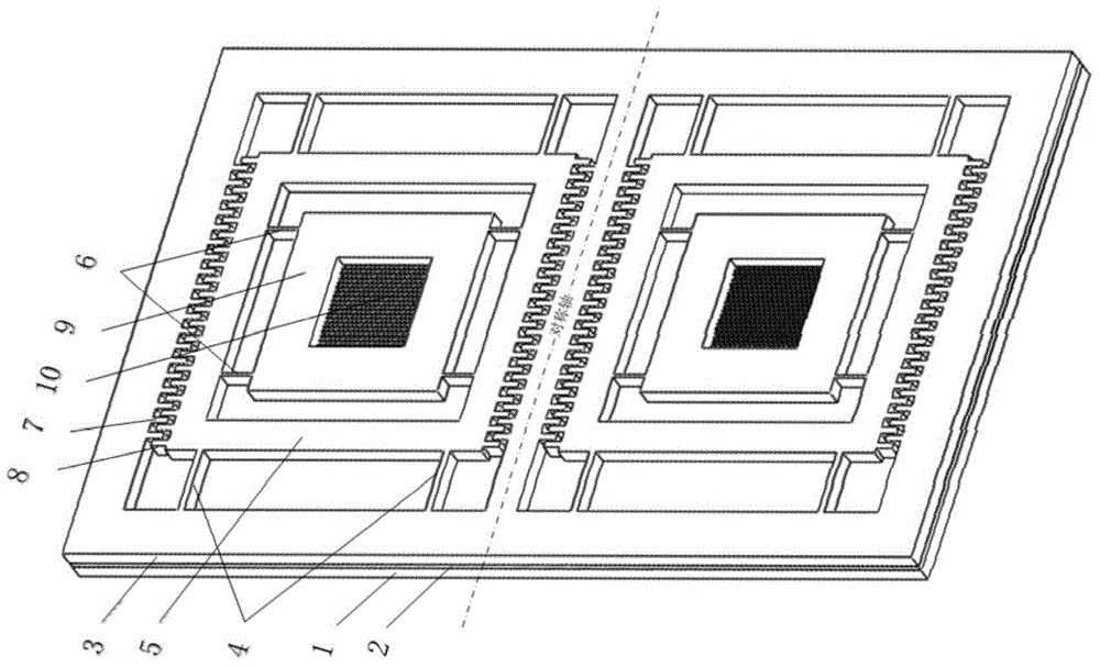
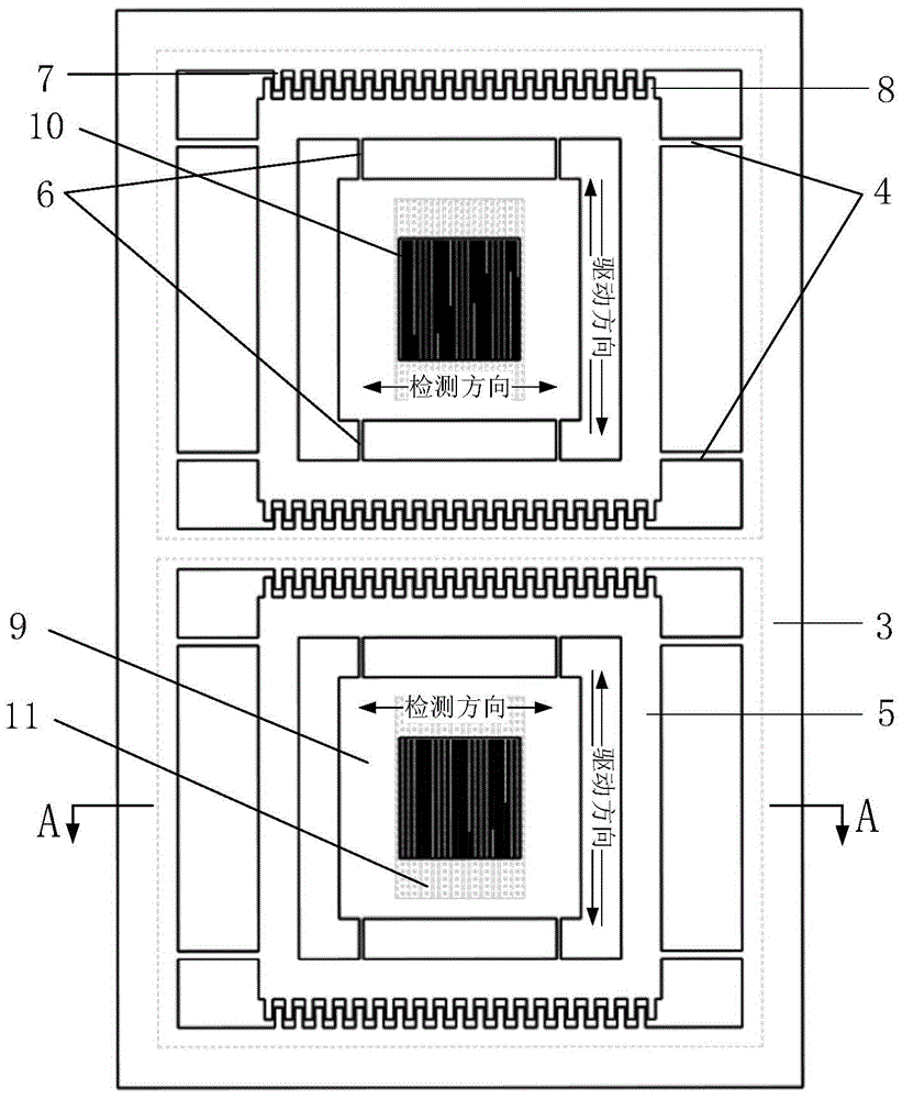
The invention discloses a novel gyroscope based on nanometer optical grating detection. The novel gyroscope comprises a bonding base plate, a gasket frame, a support frame, a driving cantilever beam, a movable frame, a detecting cantilever beam, mass blocks, a laser light source, a photoelectric conversion device and a signal detecting module. The micromachining gyroscope is symmetrical in the whole structure, two mass blocks are opposite in the driving directions, differential coupling output is realized, the structure is reasonable and compact, the nanometer optical grating is adopted, the anti-electromagnetic interference capacity is strong, and the gyroscope has the advantages of high sensitivity and good reliability.

Description

technical field [0001] The invention relates to the related field of micro-inertial navigation technology, in particular to a nano-grating-based micro-mechanical gyroscope. [0002] Background technique [0003] At present, the commonly used detection methods of MEMS gyroscopes are capacitive and piezoresistive. The piezoresistive is based on the principle of piezoresistive effect of highly doped silicon. Strong dependence, the bridge detection circuit composed of pressure sensitive devices will also cause sensitivity drift due to temperature changes; the improvement of capacitive precision is to increase the capacitance area, due to the miniaturization of the device, its accuracy depends on the effective capacitance It is difficult to improve due to the reduction of the area. [0004] The measurement of the angular velocity of the micromechanical gyroscope is completed by the force-electricity conversion of the detection device. The main method is the micro-displacement d...

Claims


Application Information

Patent Timeline
IPC IPC(8): G01C19/5726
CPCG01C19/5726G01C19/5733G01C19/5747
Inventor 李孟委王莉朱京白晓晓王琪禇伟航刘俊
Owner ZHONGBEI UNIV
Why Eureka
Try Eureka