Eureka AIR delivers breakthrough ideas for toughest innovation challenges, trusted by R&D personnel around the world.

Real-time low speed detection device and method based on DSP quadrature encoding

An orthogonal coding and detection device technology is applied in the field of real-time low-speed detection devices based on DSP quadrature coding, which can solve the problems of inability to realize rapid extraction of rotation speed, single detection of rotation speed signals, and inability to judge signals, and achieves continuous and efficient calculation. Real-time, fast speed calculation, easy modular processing effect

Inactive Publication Date: 2014-02-05
RENERGY ELECTRIC TIANJIN
View PDF3 Cites 18 Cited by
  • Summary
  • Abstract
  • Description
  • Claims
  • Application Information

AI Technical Summary

Problems solved by technology

[0007] However, no matter it is M method, T method or M / T method, encoder pulse must be required. Encoder pulse must appear twice to calculate and extract the speed, and the speed calculation value is due to 0-1 at the moment when the second pulse appears. There are speed steps or jitters in the change, so it is impossible to quickly extract the speed
[0008] Most of today's equipment and instruments, in real-time systems that use rotational speed as closed control, must require real-time and fast calculation of rotational speed, which cannot be satisfied by existing algorithms
[0009] In addition, for most speed algorithms, only a single detection is performed on the speed signal, and the signal cannot be judged, so the speed system that has tended to be stable drifts slowly until it fails

Method used


Image

  • Real-time low speed detection device and method based on DSP quadrature encoding
  • Real-time low speed detection device and method based on DSP quadrature encoding
  • Real-time low speed detection device and method based on DSP quadrature encoding

Examples


Embodiment Construction

[0053] Further illustrate the present invention below in conjunction with accompanying drawing.

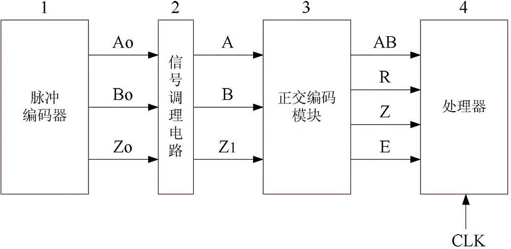
[0054] Such as figure 1 As shown, the real-time low-speed detection device based on DSP quadrature encoding provided by the present invention includes: pulse encoder 1, signal conditioning circuit 2, orthogonal encoding module 3 and processor 4; wherein: pulse encoder 1 is a velocity sensor, by The photoelectric encoder or electromagnetic encoder installed on the motor shaft is composed of three sets of differential pulse signals, Ao, Bo, and Zo, where pulse Ao and pulse Bo are quadrature pulses with a phase difference of 90 degrees, and pulse Zo is a return-to-zero pulse. That is, the encoder outputs a pulse Zo after one rotation;

[0055] The signal conditioning circuit 2 is a pulse shaping circuit module. Since the encoder signal cannot be directly used by the digital processor after it is generated, it is necessary to filter and reduce the amplitude of the three-way signal. F...


PUM


Abstract

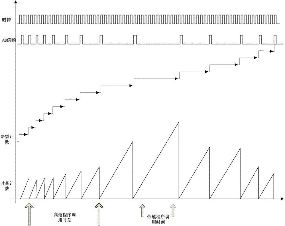
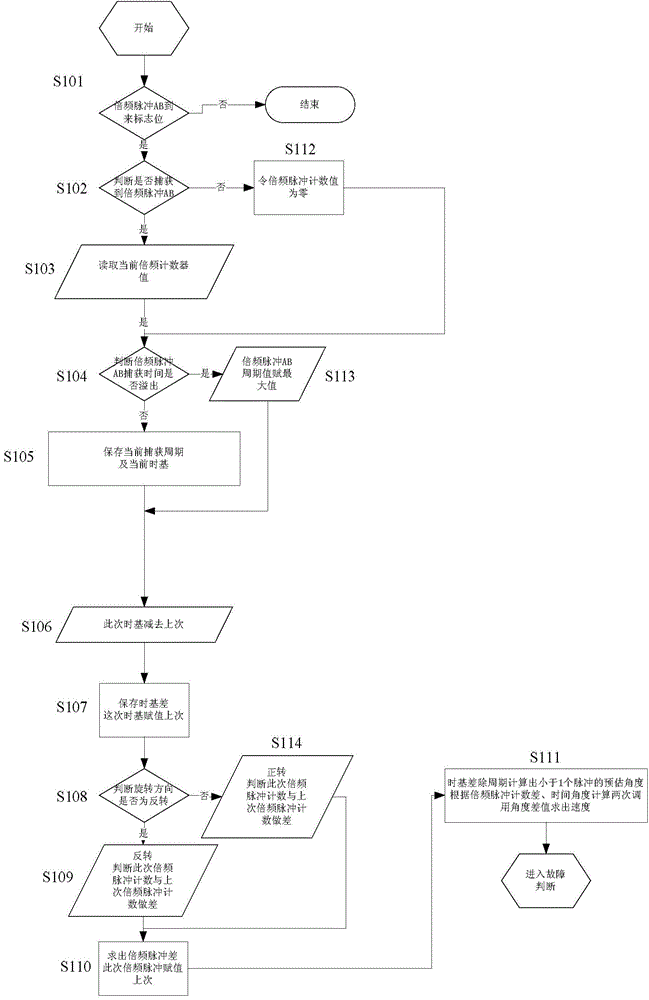
Provided are a real-time low speed detection device and method based on DSP quadrature encoding. The device comprises a pulse encoder, a signal conditioning circuit, a quadrature encoding module and a processor. The pulse encoder outputs difference pulse signals Ao, difference pulse signals Bo and difference pulse signals Co, the pulse signals Ao, the pulse signals Bo and the pulse signals Co, output from the pulse encoder, are input to three input ends of the quadrature encoding module respectively through the signal conditioning circuit, and the four output ends of the quadrature encoding module are respectively connected with the processor. The device and method have the advantages that by the adoption of the technical scheme, calculation of the rotating speed is faster, meanwhile interruption and a DSP internal counter are adopted in the whole calculation mode, and CPU time is not occupied; meanwhile, the mode of the rotating speed is used, so detection at a high speed, at a low speed and at an ultralow speed can be achieved at the same time, and the former method of calculation of the rotating speed can be completely replaced; in addition, the method has continuity and timeliness of calculated quantity, encapsulation of functions can be conducted, and modularized processing of software is facilitated.

Description

technical field [0001] The invention belongs to the technical field of signal detection, in particular to a real-time low-speed detection device and method based on DSP orthogonal coding. Background technique [0002] In the prior art, there are two speed measurement methods, analog circuit hardware detection and digital circuit calculation speed measurement. With the development of electronic information technology, especially the generation of DSP digital processing chips, the accuracy and range of speed detection have been greatly improved. There are also different methods for digital circuit speed measurement. The initial method is to use the peripheral analog-to-digital conversion chip to convert the analog quantity detected by the analog-digital conversion chip into a digital quantity, and then transmit the digital quantity to the CPU through the bus for calculation. . Now, with the development of chip technology, an analog-to-digital conversion chip will be integrat...

Claims


Application Information

Patent Timeline
IPC IPC(8): G01P3/481G01P3/486
Inventor 董晓光周玲玲朱常在
Owner RENERGY ELECTRIC TIANJIN
Why Eureka
Eureka Blog
Learn More