Controlled starting circuit

A start-up circuit and resistor technology, applied in the direction of electrical components, output power conversion devices, etc., can solve the problems of large size and weight, can not prevent self-excited oscillation, high input voltage, etc., achieve light weight, simple structure, prevent self-excited Shock effect

Active Publication Date: 2014-02-05
STATE GRID CORP OF CHINA +1
View PDF4 Cites 3 Cited by
  • Summary
  • Abstract
  • Description
  • Claims
  • Application Information

AI Technical Summary

Problems solved by technology

There are roughly two ways to control the supply of starting power. The output voltage detection power supply common circuit and the PWM (pulse width modulation) circuit power supply, and the output voltage detection power supply common circuit auxiliary power inverter has many circuit components. When using a frequency transformer, the size and weight are relatively large, which cannot prevent self-excited oscillation
[0004] The PWM circuit and the power supply of the output voltage detection circuit are independent circuits. This circuit is powered by the auxiliary winding of the main transformer after the inverter is started, and the secondary side voltage is also powered by the auxiliary winding. The disadvantage is that the primary and secondary sides need to be isolated. , resulting in a higher input voltage, which cannot be applied to the integrated controller

Method used


Image

  • Controlled starting circuit

Examples


Embodiment Construction

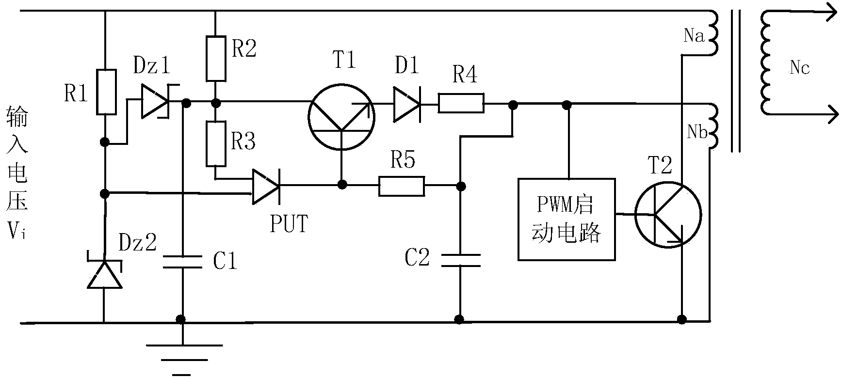
[0016] figure 1 is a schematic circuit diagram of the controlled starting circuit of the present invention, as shown in the figure, the controlled starting circuit of the present invention includes:

[0017] The first resistor R1, the second resistor R2, the third resistor R3, the fourth resistor R4, the fifth resistor R5, the first capacitor C1, the second capacitor C2, the first diode D1, the first regulator tube Dz1, the first Two regulator tubes Dz2, first transistor T1, second transistor T2, PWM starting circuit, controllable precision voltage regulator PUT, transformer winding.

[0018] Wherein, one end of the first resistor R1 is respectively connected to one end of the second resistor R2 and one end of the primary winding Na of the transformer, and the one end of the first resistor R1 receives an input signal, and the input signal is 100-150V DC voltage, the other end of the first resistor R1 is respectively connected to the anode of the first voltage regulator tube D...


PUM


Abstract

The invention relates to a controlled starting circuit which comprises a first resistor, a second resistor, a third resistor, a fourth resistor, a fifth resistor, a first capacitor, a second capacitor, a first diode, a first voltage-stabilization pipe, a second voltage-stabilization pipe, a first transistor, a second transistor, a PWM starting circuit, a controllable precision voltage-stabilization source and a transformer winding. The controlled starting circuit is simple in structure, light in weight and easy to minimize, delay time exists between inputting of external signals and starting of the PWM starting circuit, and the delay performance can effectively prevent self-excitation vibration.

Description

technical field [0001] The invention relates to the field of circuit control, in particular to a controlled starting circuit. Background technique [0002] After the switch regulated power supply (hereinafter referred to as the switching power supply) came out, it gradually replaced the linear regulated power supply and the thyristor phase-controlled power supply in many fields. The series switching power supply appeared in the early stage, and its main circuit topology is similar to that of a linear power supply, but the power transistor works in a switching state. [0003] The control circuit of the switching regulated power supply has become very simple due to the development of integrated chip technology, and the power supply of this integrated circuit is greatly affected by the circuit composition, the number of components and the packaging area. There are roughly two ways to control the supply of starting power. The output voltage detection power supply common circuit...

Claims


Application Information

Patent Timeline
Patent Type & Authority Applications(China)
IPC IPC(8): H02M1/36
Inventor 蔡普申王启银王少玮王晓强古珑赵锐黄国楠
Owner STATE GRID CORP OF CHINA
Why Eureka
Try Eureka