
Method for Selective Desulfurization of Synthetic Raw Gas

A selective, scrubbing technology used in separation methods, chemical instruments and methods, removal of gaseous pollutants, etc.

Active Publication Date: 2017-12-15
LINDE AG
View PDF3 Cites 0 Cited by
  • Summary
  • Abstract
  • Description
  • Claims
  • Application Information

AI Technical Summary

Problems solved by technology

Therefore, sulfur-free gas mixtures may only be suitable for gas turbines with limited

Method used


Image

  • Method for Selective Desulfurization of Synthetic Raw Gas

Examples


Embodiment Construction

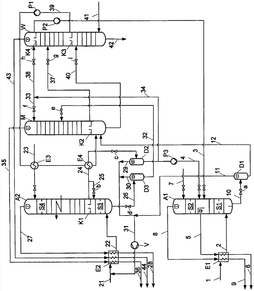
[0017] In order to obtain fuel for the gas turbine, unconverted raw synthesis gas 1 containing, in addition to hydrogen and carbon monoxide, also carbon dioxide and sulfur components is led into the heat exchanger E1 and cooled there opposite the process stream to be heated, It can then be fed via line 2 into the lower region of the scrubber A1 designed as an absorption column. In the absorption column A1, which typically operates at a pressure between 20 and 80 bar and comprises a first scrubbing zone S1 and a second scrubbing zone S2, the cooled synthesis raw gas flows upwards and is here connected with the supply via lines 3 and 4 The methanol detergent to the upper end of the washing zone S1 comes into intense contact. The two sulfur-free methanol streams 3 and 4 are pre-loaded with carbon dioxide and enter scrubbing zone S1 at a higher partial pressure of carbon dioxide than the synthetic crude gas 2 to be scrubbed, so although the carbon dioxide partial pressure from the...


PUM


Abstract

The invention relates to a method for operating a gas scrubber in which a feed gas containing hydrogen, carbon monoxide, carbon dioxide and carbon oxysulfide and / or hydrogen sulfide is scrubbed in a scrubber (A1) with a scrubbing agent (3, 4) preloaded with carbon dioxide (1), thereby substantially selectively separating sulfur components from the feed gas and producing a desulfurized gas stream (5, 9). The invention is characterized in that sulfur-free scrubbing agents (3, 4) are used whose partial pressure of carbon dioxide is equal to or greater than the partial pressure of carbon dioxide in the feed gas (1) to be desulfurized when it is introduced into the scrubber (A1) pressure.

Description

technical field [0001] The invention relates to a method for operating a gas scrubber in which a feed gas containing hydrogen, carbon monoxide, carbon dioxide and carbon oxysulfide and / or hydrogen sulfide is scrubbed in a scrubber by means of a scrubbing agent preloaded with carbon dioxide, thereby essentially selecting The sulfur components are selectively separated from the feed gas and a sweetened gas stream is produced. Background technique [0002] In the context of this description, a sweetened gas stream is to be understood as a gas stream in which the content of sulfur components is below a predetermined limit value. It does not need to be completely free of sulfur, nor could it be achieved with reasonable complexity. [0003] Gas scrubbers are used to wash out specific components from gas mixtures. Scrubbing equipment takes full advantage of the property of liquids to absorb gaseous substances and keep them in solution in a chemical or physical combination. The d...

Claims


Application Information

Patent Timeline
Patent Type & Authority Patents(China)
IPC IPC(8): C10K1/16
CPCB01D53/1468C10K1/004C10K1/16C10K3/04B01D2252/2021B01D2252/2026B01D2252/20468B01D2252/20478B01D2256/16B01D2256/20B01D2256/22B01D2257/304B01D2257/308B01D53/14
Inventor A·布兰德尔A-M·菲舍尔
Owner LINDE AG
Learn More