
Method for forming, by CVD, nanostructures of semi-conductor material of homogeneous and controlled size on dielectric material

a technology of semiconductor materials and nanostructures, which is applied in the direction of nanotechnology, crystal growth process, chemical vapor deposition coating, etc., can solve the problems of affecting the correct operation of the device, limiting the quality and performance of the device based on the structure, and high dispersion in size, around 50%, of silicon nanocrystals

Active Publication Date: 2004-07-29
COMMISSARIAT A LENERGIE ATOMIQUE ET AUX ENERGIES ALTERNATIVES
View PDF4 Cites 21 Cited by
  • Summary
  • Abstract
  • Description
  • Claims
  • Application Information

AI Technical Summary

Benefits of technology

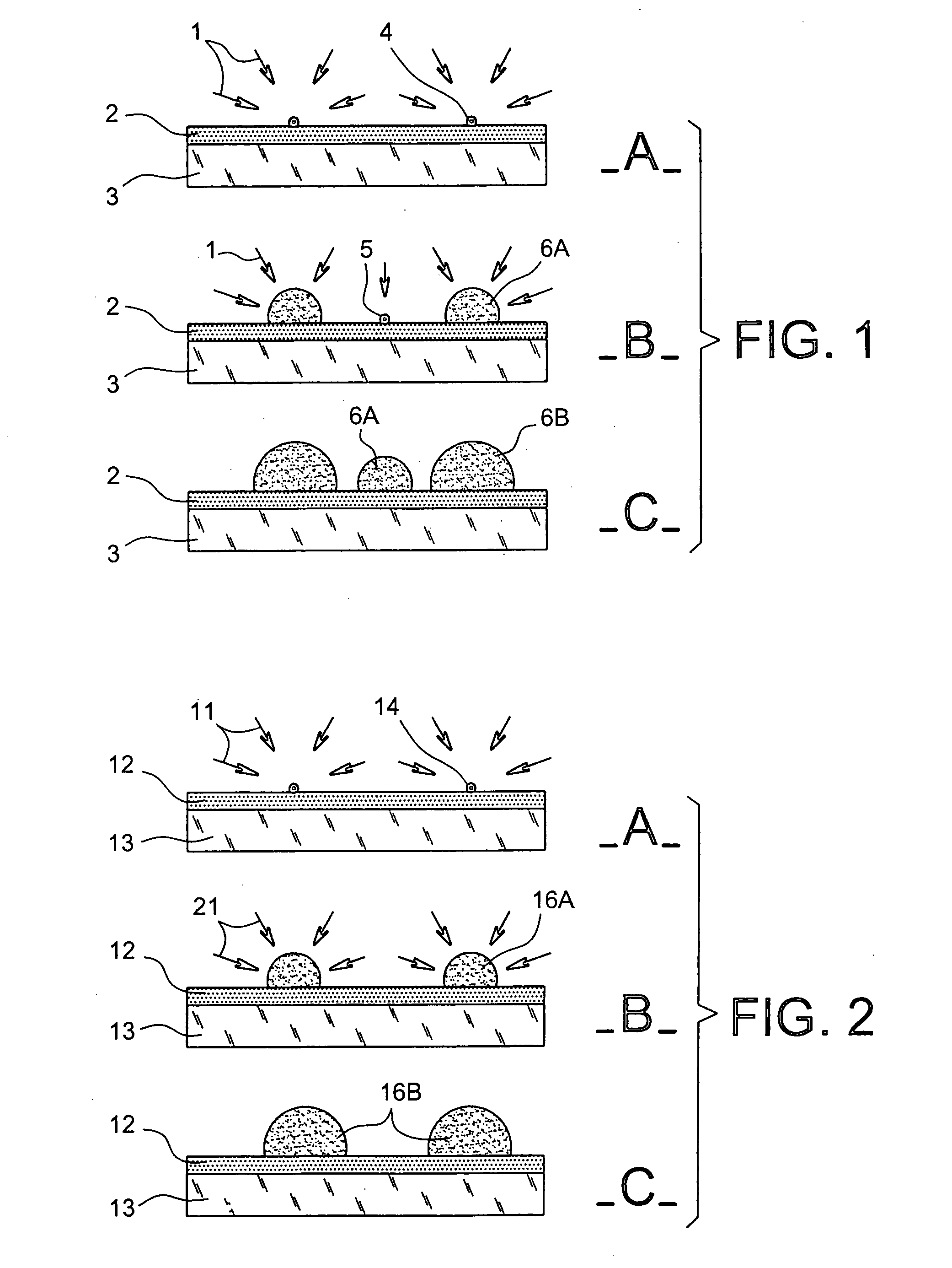
[0024] In other words, the method according to the invention makes it possible, firstly, to deposit nanostructures of germanium isolated from each other on a dielectric material by CVD; if the substrate of dielectric material is in silica and one uses germane as precursor of germanium, one does not need, thanks to said method, to deposit an intermediate continuous layer of silicon on the substrate of dielectric material of silica. By said method, the nanostructures have a homogeneous and controlled size, and their density varies between 10.sup.9 and some 10.sup.12 / cm.sup.2. Advantageously, by playing on the temperature and pressure parameters of the precursor during the deposition, one can obtain either crystalline or amorphous nanostructures.
[0028] Advantageously, the step of forming stable nuclei of a first semi-conductor material is carried out for an exposure time chosen as a function of the desired density of nuclei; the longer the exposure time, the higher the density of nuclei.
[0030] Advantageously, the CVD steps are carried out with a low partial pressure of precursor. Indeed, if the partial pressure of the precursors is low, the rate of growth of the nuclei is low and one can thus control more easily the size of the nanostructures.
[0047] It should be noted that, in the case of germanium nanostructures, the purity of the nanostructures obtained is high since the size of the nuclei formed during the first CVD step is small compared to that of the final nanostructures.
[0048] Thanks to said method, the average size of the silicon nanostructures may be controlled with precision and may be modified easily without having to change the deposition conditions: it is sufficient to modify the deposition time of the second step in order to have nanostructures of the desired size. On the other hand, in the case of a method in a single step, a modification of the deposition time would lead to a modification of the average size of the nanostructures, but also of their density. Consequently, it would be necessary to modify the deposition conditions, pressure and temperature in order to obtain the desired density of silicon nanostructures.

Problems solved by technology

However, in the short or medium term, the SIA Roadmap provides for a gate length of around 35 nm, beyond which quantum effects will disrupt its correct operation.
The main limitation of this technique is the high dispersion in size, around 50%, of the silicon nanocrystals.
This has the effect of limiting the quality and the performance of devices based on said structures.

Method used


Image

  • Method for forming, by CVD, nanostructures of semi-conductor material of homogeneous and controlled size on dielectric material
  • Method for forming, by CVD, nanostructures of semi-conductor material of homogeneous and controlled size on dielectric material

Examples


first embodiment

[0022] the first and second semi-conductor materials are in silicon.

second embodiment

[0023] the first semi-conductor material is in silicon and the second semi-conductor material is in germanium.

[0024] In other words, the method according to the invention makes it possible, firstly, to deposit nanostructures of germanium isolated from each other on a dielectric material by CVD; if the substrate of dielectric material is in silica and one uses germane as precursor of germanium, one does not need, thanks to said method, to deposit an intermediate continuous layer of silicon on the substrate of dielectric material of silica. By said method, the nanostructures have a homogeneous and controlled size, and their density varies between 10.sup.9 and some 10.sup.12 / cm.sup.2. Advantageously, by playing on the temperature and pressure parameters of the precursor during the deposition, one can obtain either crystalline or amorphous nanostructures.

[0025] Furthermore, the invention also makes it possible to deposit, on a dielectric material, nanostructures of silicon isolated fro...


PUM

PropertyMeasurementUnit
temperatureaaaaaaaaaa
partial pressuresaaaaaaaaaa

Abstract

The invention concerns a method for forming nanostructures of semi-conductor material on a substrate of dielectric material by chemical vapour deposition (CVD). Said method comprises the following steps: a step of forming on the substrate (12) stable nuclei (14) of a first semi-conductor material in the form of islands, by CVD from a precursor (11) of the first semi-conductor material chosen so that the dielectric material (12) accepts the formation of said nuclei (14), a step of forming nanostructures (16A, 16B) of a second semi-conductor material from the stable nuclei (14) of the first semi-conductor material, by CVD from a precursor (21) chosen to generate a selective deposition of the second semi-conductor material only on said nuclei (14). The invention further concerns nanostructures formed according to one of said methods as well as devices comprising said nanostructures.

Description

[0001] This application claims priority to French application no. 02 14658, filed on Nov. 22, 2002, entitled: "A Method For Forming, by CVD, Nanostructures of Semi-Conductor Material of Homogenous and Controlled Size on Dielectric Material" and was not published in English.[0002] The invention concerns a method for forming nanostructures of semi-conductor material on a dielectric material by chemical vapour deposition (CVD), said nanostructures being of homogeneous and controlled size. The semi-conductor material is, in particular, silicon or germanium.[0003] The invention further concerns devices with nanostructures obtained by means of the method according to the invention.[0004] The nanostructures formed in this way are intended for forming electronic, optic or opto-electronic devices and, in particular, for forming Coulomb blockade devices that use quantum dots.[0005] The applications targeted in particular by the present invention are granular gate storage cells and DOTFET, whi...

Claims


Application Information

Patent Timeline
Patent Type & Authority Applications(United States)
IPC IPC(8): B82B3/00C23C16/04C30B25/00C30B25/02H01L21/20H01L21/205H01L21/28H01L21/285H01L21/8247H01L27/10H01L27/115H01L29/06H01L29/423H01L29/49H01L29/66H01L29/788H01L29/792
CPCB82Y10/00Y10S438/967C30B25/00C30B25/02H01L21/0242H01L21/02422H01L21/0245H01L21/02513H01L21/02532H01L21/0259H01L21/0262H01L21/02639H01L21/02645H01L21/28273H01L29/0665H01L29/0673C23C16/04C30B29/605H01L29/40114
Inventor MAZEN, FREDERICBARON, THIERRYHARTMANN, JEAN-MICHELSEMERIA, MARIE-NOELLE
Owner COMMISSARIAT A LENERGIE ATOMIQUE ET AUX ENERGIES ALTERNATIVES
Learn More