Melt differential electrostatic spinning device and process

A technology of melt differentiation and electrospinning, which is applied in textiles and papermaking, filament/thread forming, fiber processing, etc. It can solve the problems that are difficult to be suitable for industrial application, complex structure, high energy consumption, etc., and achieve simple device and process Ease of operation, simple structure and high output

Inactive Publication Date: 2014-02-12
BEIJING UNIV OF CHEM TECH
View PDF7 Cites 20 Cited by
  • Summary
  • Abstract
  • Description
  • Claims
  • Application Information

AI Technical Summary

Problems solved by technology

[0006] The above melt electrospinning devices are not only complex in structure, but also high in e

Method used


Image

  • Melt differential electrostatic spinning device and process
  • Melt differential electrostatic spinning device and process
  • Melt differential electrostatic spinning device and process

Examples


Embodiment 1

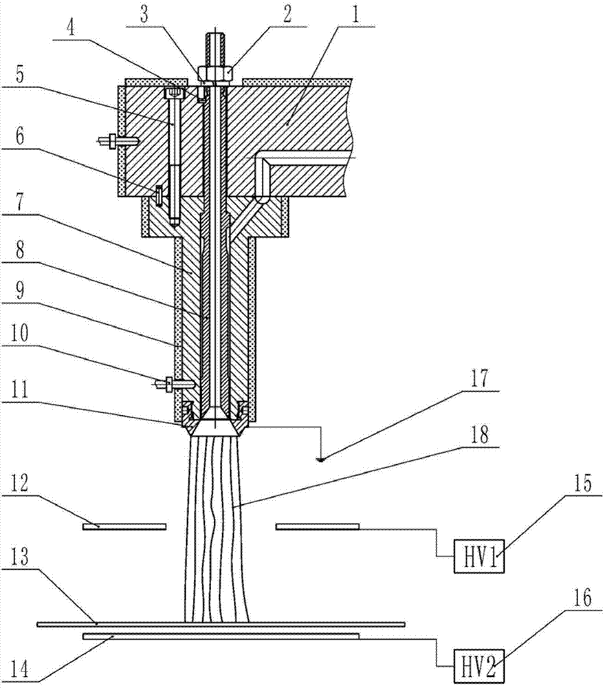
[0030] Such as figure 1As shown, the melt differential electrospinning device of the present invention mainly includes a melt differential electrospinning nozzle and a multi-electric field coupling strong drafting device.

[0031] The melt differential electrospinning nozzle is mainly composed of a splitter plate 1, a nut 2, a spring washer 3, an air duct positioning pin 4, a screw 5, a nozzle body positioning pin 6, a nozzle body 7, an air duct 8, a heating device 9, and a temperature sensor 10. Cone nozzle 11 and ground electrode 17. The nozzle body 7 and the distribution plate 1 are positioned by the nozzle body positioning pin 6 and connected with the screw 5. The inlet of the inclined flow channel on the nozzle body 7 communicates with the outlet of the distribution channel on the distribution plate 1; the air duct 8 is installed on the nozzle body 7 and the distribution channel In the inner hole of the plate 1, there is an annular gap between the outer surface of the ai...

Embodiment 2

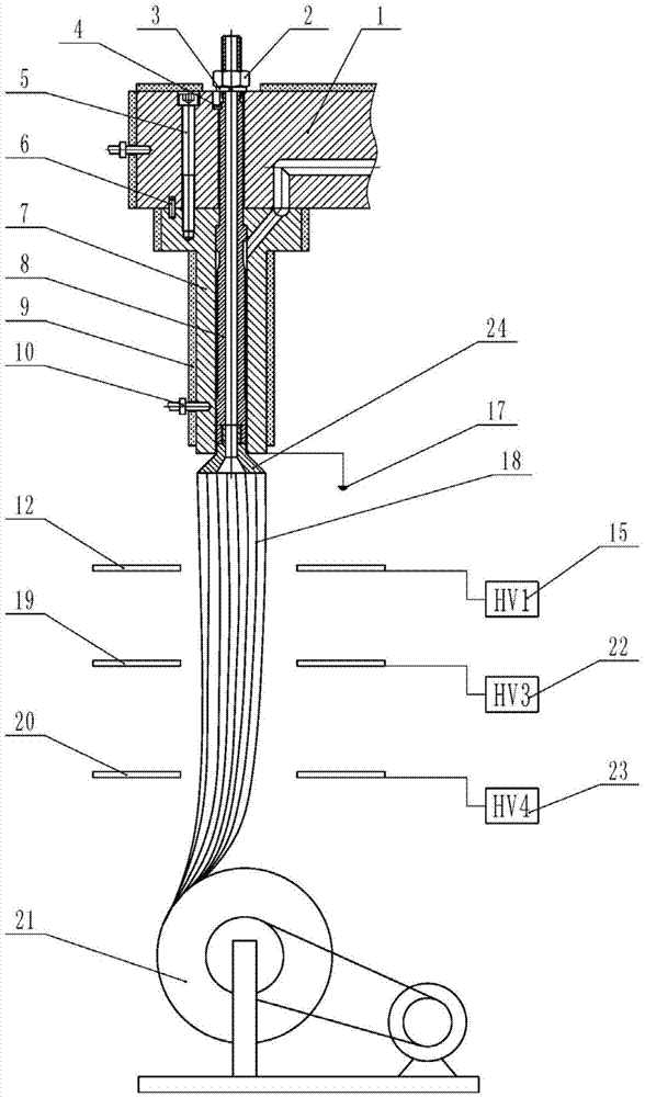
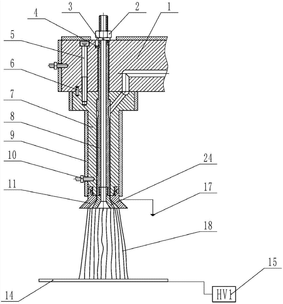
[0036] Such as figure 2 As shown, the structure, working principle and effect of this embodiment are basically the same as those of Embodiment 1, the difference is that in the melt differential electrospinning nozzle, the inner cone nozzle 11 can also be replaced with the outer cone nozzle 24, and the outer cone nozzle The surface nozzle 24 is connected to the bottom end of the air duct 8 through threads, the nozzle body 7 is connected to the ground electrode 17, and the rest of the structure is the same as that of the aforementioned melt differential electrospinning nozzle.

[0037] The multi-electric field coupling strong drafting device is composed of three layers of electrode plates. The outer cone nozzle 24 is equipped with electrode plate 1 12, electrode plate 3 19, and electrode plate 4 20 in turn. The three electrode plates are electrode plates with holes in the middle. , the electrode plate one 12 is connected with the high-voltage positive terminal of the high-volta...


PUM


Abstract

The invention discloses a melt differential electrostatic spinning device and process. The device mainly comprises a melt differential electrostatic spinning nozzle and a multi-electric-field coupling strong drafting device, wherein the melt differential electrostatic spinning nozzle is arranged above the multi-electric-field coupling strong drafting device. The melt differential electrostatic spinning nozzle mainly comprises a spreader plate, a nut, a spring washer, an air duct locating pin, a screw, a nozzle body locating pin, a nozzle body, an air duct, a heating device, a temperature sensor, an inner cone nozzle and a grounding electrode. The multi-electric-field coupling strong drafting device mainly comprises a first plate electrode, a second plate electrode, a first high-voltage electrostatic generator, a second high-voltage electrostatic generator and a fiber receiving plate. Under the action of force of a wind field and an electric field, finally, polymer melt is differentially and evenly distributed to form dozens of Taylor cones of one circle along the edge of the conical face, then dozens of jet flow are formed and refined to be nanometer filaments, a plurality of melt differential electrostatic spinning nozzle bodies are installed below the spreader plate so as to achieve mass production of nanometer fibers, the structure is simple, and parts are easy to machine and assemble.

Description

technical field [0001] The invention relates to a melt differential electrostatic spinning device and process, belonging to the field of electrostatic spinning. Background technique [0002] With the wide application of nanotechnology, the preparation of nanofibers by electrospinning has attracted more and more attention from experimental research and industrial development. Solution electrospinning has been deeply studied and widely used due to its mild preparation process and nano-scale fiber fineness. At present, mass production has been initially realized. However, due to the use of solvents, the continuity of industrialization, production environment, and medical applications Due to the problems of toxic solvent recovery, low fiber strength with holes, difficulty in preparing PP and PE fibers and low efficiency in solution electrospinning, this limits the industrial application of solution electrospinning technology. Melt electrospinning does not use solvents and is in...

Claims


Application Information

Patent Timeline
IPC IPC(8): D01D5/00
Inventor 杨卫民钟祥烽李好义李陈宏波丁玉梅
Owner BEIJING UNIV OF CHEM TECH
Why Eureka
Try Eureka