Electromagnetic shielding effectiveness testing system under live room condition and testing method thereof

A technology of electromagnetic shielding and testing system, applied in the direction of measuring electricity, measuring devices, measuring electrical variables, etc., can solve the problems of strong randomness, poor repeatability and comparability of measurement results, occurrence of resonance phenomenon, etc., to avoid fluctuation of measurement results Too large, avoid strong randomness, and improve the effect of repeatability

Active Publication Date: 2014-02-12
PEOPLES LIBERATION ARMY ORDNANCE ENG COLLEGE
View PDF2 Cites 19 Cited by
  • Summary
  • Abstract
  • Description
  • Claims
  • Application Information

AI Technical Summary

Problems solved by technology

This traditional device has two serious defects: (1) Due to the uneven distribution of the field strength inside the cavity and even resonance phenomenon, this single-point measurement determines that the measured shielding effectiveness will be different due to the different values ​​of the field strength at different positions. There is even a big difference, which leads to strong randomness, poor repeatability and comparability of the measurement results; (2) The previous devices have clear requirements, that is, the frequency point of the measurement needs to avoid the resonance frequency of the cavity
The disadvantage of this test method is that for small-sized shielded chambers, the IEC61000-4-21 standard is no longer applicable because there is not enough space in the measured chamber to install the stirrer.
As mentioned above, there is no suitable standard and test device for the shielding effectiveness test of small-sized shielded chambers.

Method used


Image

  • Electromagnetic shielding effectiveness testing system under live room condition and testing method thereof
  • Electromagnetic shielding effectiveness testing system under live room condition and testing method thereof

Examples


Embodiment 1

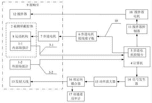
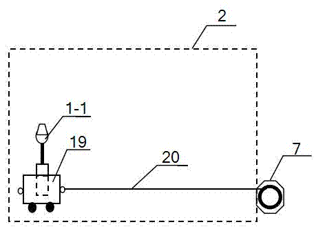
[0046] The present invention comprises a reverberation chamber 9, a transmitting antenna 13 placed in the reverberation chamber 9, an agitator 12 and a shielded cavity 2 to be tested, an agitator controller 11 controlled by a computer 4 outside the reverberation chamber 9, a signal Generator 14, power amplifier 15, double directional coupler 16, coaxial cable and dual-channel power meter 17; The output end of described computer 4 connects the GPIB control port of described signal generator 14 through GPIB cable, and described signal The output end of generator 15 connects the input end of power amplifier 15 through coaxial cable, and the output end of described power amplifier 15 connects the input end of double directional coupler 16 through coaxial cable, and the output end of described double directional coupler 16 Connect the transmitting antenna 13 through the coaxial cable, and the forward output power monitoring end and the backward reflection power monitoring end of...


PUM


Abstract

The invention discloses an electromagnetic shielding effectiveness testing system under a live room condition and a testing method thereof. The system comprises a movement mechanism in a shielding cavity to be tested and an internal field intensity meter arranged on the movement mechanism, wherein an external field intensity meter and a stepping motor are arranged between the shielding cavity to be tested and a live room, and a computer provided with a stepping motor control card controls the stepping motor through a stepping motor terminal board. The output end of the internal field intensity meter and the output end of the external field intensity meter are connected with the corresponding input ends of the computer through field intensity meter optical fibers respectively. The output end of the stepping motor control card is connected with the input end of the stepping motor terminal board through a dedicated control wire cable, and the output end of the stepping motor terminal board is connected with the stepping motor. Multi-point automatic measurement is adopted in the testing method. The electromagnetic shielding effectiveness testing system under the live room condition and the testing method thereof have the advantages that the repeatability of testing results is improved, measurement is allowed to be carried out on the resonance frequency points of the shielding cavity to be tested, a stirrer does not need to be arranged in the shielding cavity to be tested, and thus the problem that the stirrer cannot be arranged in small size shielding cavities is solved.

Description

technical field [0001] The invention relates to an electromagnetic shielding effectiveness testing system and a testing method thereof under reverberation chamber conditions, and is especially suitable for measuring the shielding effectiveness in a small-sized (line length less than 2 meters) shielding cavity under the reverberation chamber environment. Background technique [0002] Electromagnetic shielding is a direct and effective method to control radiation interference. It uses good conductors to surround interference sources or sensitive electrical appliances to isolate the surrounded parts from mutual interference with external electric, magnetic or electromagnetic fields. Electromagnetic shielding is widely used in scientific research, electronic technology, aerospace, especially military technology and other fields, and is an important research field of electromagnetic compatibility. For example, rocket systems and orbital cabins in the aerospace field, shielding sh...

Claims


Application Information

Patent Timeline
Patent Type & Authority Applications(China)
IPC IPC(8): G01R31/00
Inventor 王庆国毕军建程二威范丽思曲兆明贾锐王玉明
Owner PEOPLES LIBERATION ARMY ORDNANCE ENG COLLEGE
Why Eureka
Try Eureka