Power supply control cabinet system and operation method thereof

A power supply control and power input technology, applied in electrical program control, comprehensive factory control, comprehensive factory control, etc., can solve problems such as low work efficiency, high error rate, damage, etc., to ensure power supply quality, power supply safety, and security The effect of safe operation

Active Publication Date: 2014-02-12
南京三一光电科技有限公司
View PDF8 Cites 6 Cited by
  • Summary
  • Abstract
  • Description
  • Claims
  • Application Information

AI Technical Summary

Problems solved by technology

[0002] Traditional power supply control cabinets are composed of air switches, leakage protectors and other auxiliary materials. After assembly, electricians need a lot of wiring and handwriting with corresponding stickers to mark the definition of an air switch representative (such as lighting, air conditioning, wall sockets, etc.) ), this integration method determines its large size, complicated wiring, high error rate, and low work efficiency during installation. If it is put into use, if it is operated frequently, or the label is stained or lost, it will bring many complicated and repetitive maintenance. labor
Moreover, due to its production mode, the air switch determines that the current value it can pass is fixed, but in fact, the operating current of the electrical equipment is often far less than the rated current that the air switch can pass, so the air switch of

Method used


Image

  • Power supply control cabinet system and operation method thereof

Examples


Embodiment Construction

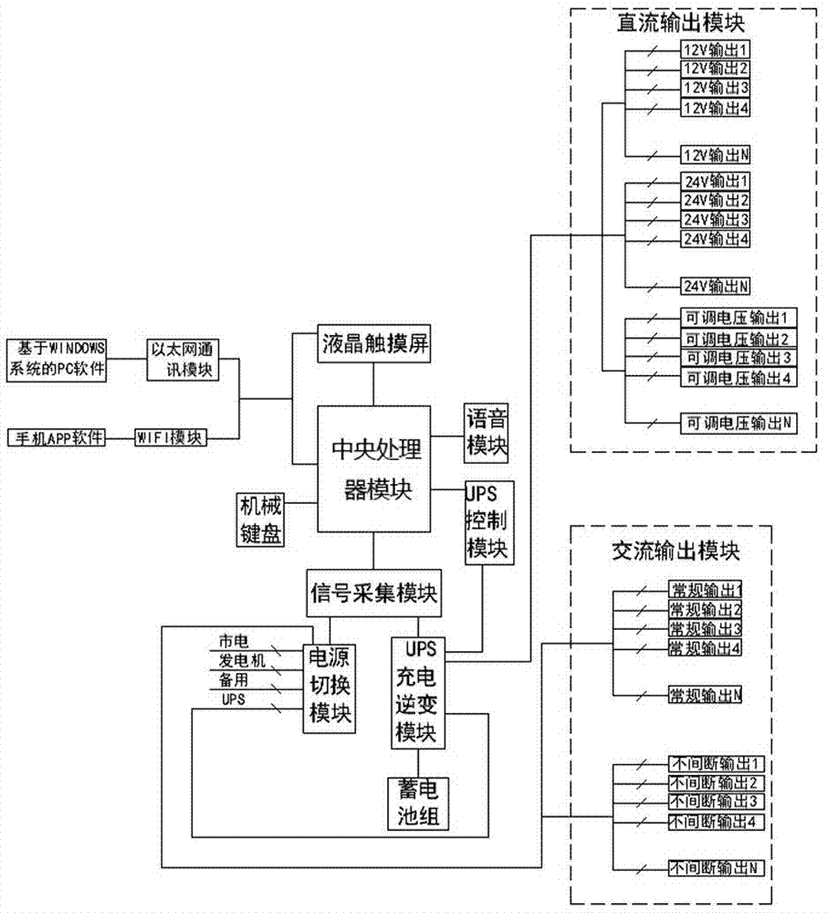
[0032] In order to clarify the technical scheme and technical effect of the present invention, the present invention will be further introduced below in conjunction with specific embodiments and accompanying drawings.

[0033] As shown in the figure, a power control cabinet system includes the following components:

[0034] 1) CPU module, built-in DSP high-speed processing unit;

[0035] 2) Network module, the central processor module establishes a connection with the upper computer system through a wireless network such as a wired LAN or WIFI, and the upper computer can be a computer or a mobile phone;

[0036] 3) A signal acquisition module, the signal acquisition module is connected to the central processing unit module. The signal acquisition module collects the electrical signals of each input channel and output channel of the power supply on site through the voltage transformer and circuit transformer, and transmits the data to the central processing module after proces...


PUM


Abstract

The invention provides a power supply control cabinet system and an operation method of the power supply control cabinet system. The power supply control cabinet system comprises a central processing unit module, a network module, a signal collection module, a displayer, an input terminal, a power input module, a power output module and a power supply switching module, wherein the power input module comprises a plurality of input channels, the power output module comprises a direct-current output module and an alternating-current output module, and the power supply switching module is connected with the power input module and switches a corresponding power supply loop into a system circuit according to user hand-operated selection or system presetting or a signal analysis result. By means of real-time monitoring of a central processing unit and a signal collection device, the defect that a traditional control cabinet is low in control accuracy is overcome in terms of input control and output control of power supplies, the situation that the over-current and the under voltage happen to circuit and other situations can be timely prevented, safety performance of a circuit system is effectively ensured, and meanwhile power supply safety and power supply quality of the system is ensured by setting multiple modes to conduct selection and switching on the power supplies.

Description

technical field [0001] The invention belongs to the technical field of electric power system automation control, and in particular relates to a power supply control cabinet system and an operation method thereof. Background technique [0002] Traditional power supply control cabinets are composed of air switches, leakage protectors and other auxiliary materials. After assembly, electricians need a lot of wiring and handwriting with corresponding stickers to mark the definition of an air switch representative (such as lighting, air conditioning, wall sockets, etc.) ), this integration method determines its large size, complicated wiring, high error rate, and low work efficiency during installation. If it is put into use, if it is operated frequently, or the label is stained or lost, it will bring many complicated and repetitive maintenance. labor. Moreover, due to its production mode, the air switch determines that the current value it can pass is fixed, but in fact, the ope...

Claims


Application Information

Patent Timeline
IPC IPC(8): G05B19/418
CPCY02P90/02
Inventor 张灿锋
Owner 南京三一光电科技有限公司
Why Eureka
Try Eureka