Pneumatic emulsification treatment device

A processing device and pneumatic emulsification technology, applied in chemical instruments and methods, dispersed particle separation, separation methods, etc., can solve the problems of harsh on-site environment, difficult operation, large dust, etc., to reduce operating parameters, reduce equipment scale, The effect of improving desulfurization capacity

Pending Publication Date: 2020-05-29
株洲舒创环保技术有限公司
View PDF0 Cites 0 Cited by
  • Summary
  • Abstract
  • Description
  • Claims
  • Application Information

AI Technical Summary

Problems solved by technology

[0014] 1. Quality control issues. Compared with factory processing and production, due to cost and site reasons, on-site production has several factors that affect the quality of production and safety:
[0015] (1) Non-ferrous smelting and iron and steel metallurgical plants have limited space, and it is difficult to fully roll out the production;
[0016] (2) The level of blanking, welding, installation and derusting of the hired production personnel cannot be fully controlled;
[0017] (3) According to the construction period, the possible construction quality management regulations cannot be well implemented. For example, the use of special welding rods requires insulation of the welding rods, welding slag should be cleaned, some parts need to be pickled, and some platforms and stairs need to be brushed. 3-4 coats of paint for protection have not been carefully implemented;
[0018] (4) The on-site environment is harsher than that of the factory, and the on-site factory areas such as iron and steel metallurgy and non-ferrous smelting are dusty and dusty, which makes it impossible to guarantee the cleaning of materials in place during production
Subsequent processing leads to unstable quality of finished products
[0019] 2. Safety issues. According to local environmental protection requirements, environmental protection facilities (including chimneys) are not less than tens of meters, and operations such as high-altitude hoisting and welding are difficult. If management is not in place, safety accidents are prone to occur; there are various media on site , if leakage occurs, it is also prone to safety accidents
[0020] 3. The problem of construction period. For general desulfurization projects, in terms of pneumatic emulsification desulfurization system, the total construction period is 2-4 months, including 20-30 days design period, 20-30 days civil construction period, and 30-50 days construction period. Equipment production and installation period; and for the spray desulfurization system, the total construction period is 6 months, and the equipment production and installation period needs more than 60 days (including anti-corrosion process in the desulfurization tower production process), no matter which way, it requires a lot of construction Time, which greatly affects the owner's planned production
[0021] Fifth, the above-mentioned 316L stainless steel is the mainstream material for making the pneumatic emulsification desulfurization tower, but because the original design of the desulfurization tower is welded connection, it is impossible to use other high-performance but unweldable materials according to the specific working conditions of the flue gas, such as electroplating composite materials, ceramics, etc., resulting in the inability of the pneumatic emulsification desulfurization tower to use electroplating composite materials, ceramics or other materials that are not suitable or cannot be welded, which limits the promotion of pneumatic emulsification technology, and cannot use special products that can effectively reduce costs according to actual flue gas conditions. material

Method used


Image

  • Pneumatic emulsification treatment device
  • Pneumatic emulsification treatment device
  • Pneumatic emulsification treatment device

Examples


Embodiment Construction

[0062] In order to enable those skilled in the art to better understand the solution of the present invention, the present invention will be further described in detail below in conjunction with the accompanying drawings and specific embodiments.

[0063] In this article, terms such as "front, back, inside, and outside" are established based on the positional relationship shown in the drawings. Depending on the drawings, the corresponding positional relationship may also change accordingly. It is understood as an absolute limitation on the scope of protection; moreover, relative terms such as "first" and "second" are only used to distinguish one from another component with the same name, and do not necessarily require or No such actual relationship or order between these components is implied.

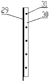
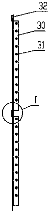
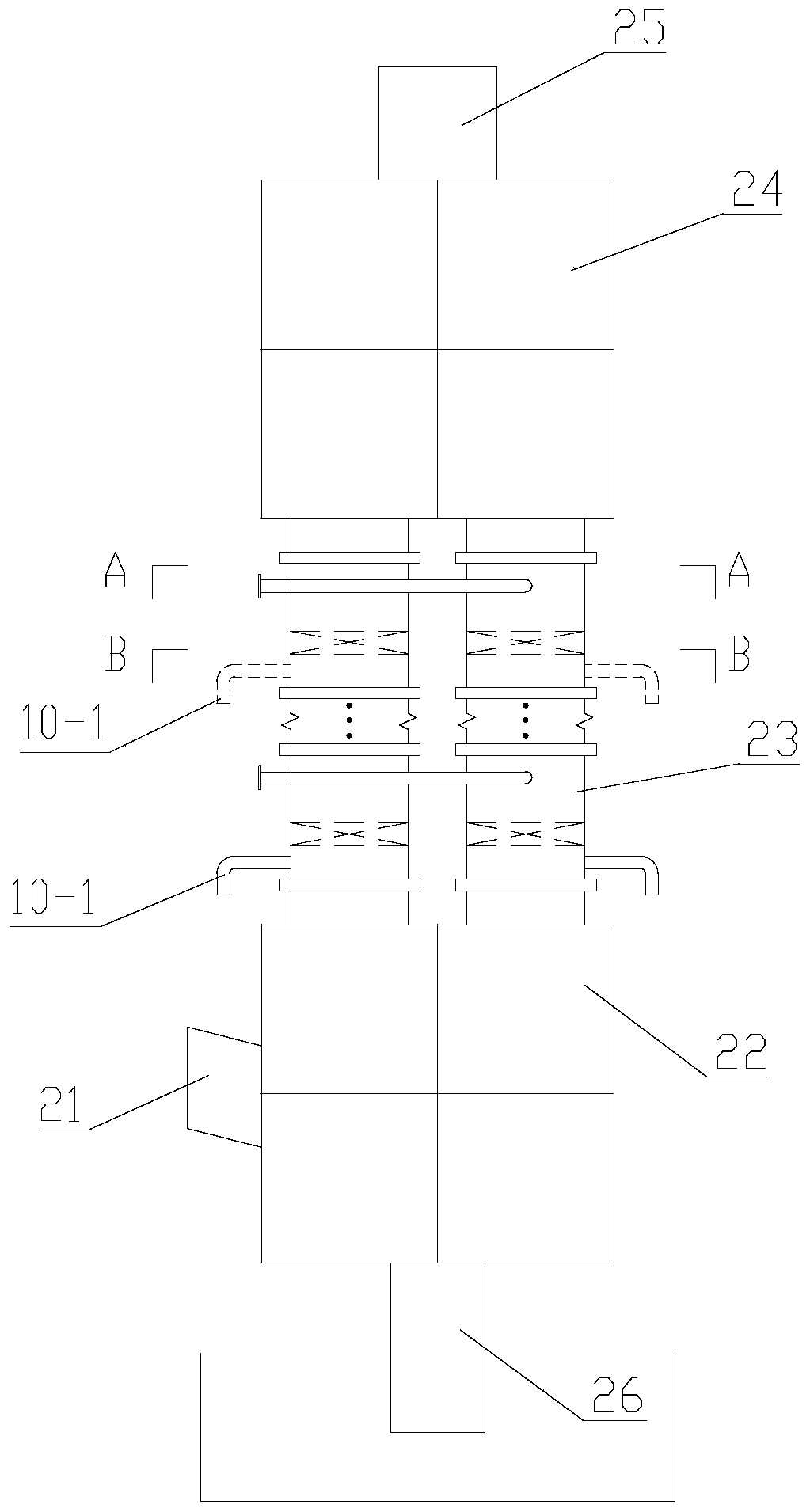
[0064] The principle of pneumatic emulsification when a typical purification element is running is as follows: In the circular tubular device of the purification element, the accelerat...


PUM


Abstract

The invention discloses a pneumatic emulsification treatment device. The device comprises a gas homogenizing chamber, a purification element section and a demisting chamber, wherein the lower end of the purification element section is communicated with the gas homogenizing chamber, the upper end of the purification element section is communicated with the demisting chamber, the purification element of the purification element section comprises a cyclone cylinder and a cyclone, the cyclone cylinder comprises an inner cylinder and an outer cylinder, and the cyclone is arranged in the inner cylinder. A slurry discharging space is formed between the inner cylinder and the outer cylinder, the inner cylinder is provided with a slurry feeding port, and a slurry discharging part is arranged on theside wall, located between the slurry feeding port and the cyclone, of the inner cylinder; the shell parts of the gas homogenizing chamber and the demisting chamber are respectively of a split assembled structure and comprise a plurality of wall plates which are distributed in the horizontal direction and the vertical direction, each wall plate is a factory prefabricated part, and the adjacent wall plates are connected through a non-welded assembly structure. The device can effectively solve the problems of large operation resistance, long construction period and the like.

Description

technical field [0001] The invention relates to the technical field of flue gas purification equipment, in particular to a processing device for purifying flue gas from equipment such as industrial kilns and boilers by using the principle of pneumatic emulsification. Background technique [0002] As the most widely used desulfurization technology, wet flue gas desulfurization accounts for almost 85% of the total global desulfurization installed capacity. There are more than 200 specific implementation methods, most of which are inseparable from nozzles, such as empty tower spray, Venturi, rotary, etc. Flow plate tower, bubbling tower, turbulent ball tower, perforated plate tower, water film tower, etc., are all inseparable from the spray distribution liquid, and according to the principle of aerodynamics, the researched and developed pneumatic emulsification desulfurization tower is the only one on the market that does not Wet flue gas cleaning installations that require liq...

Claims


Application Information

Patent Timeline
Patent Type & Authority Applications(China)
IPC IPC(8): B01D53/50B01D53/80
CPCB01D53/501
Inventor 舒梅男
Owner 株洲舒创环保技术有限公司
Why Eureka
Try Eureka