
Composite intermediate reflective layer for battery and multi-junction multi-stacked silicon-based thin film battery

A technology of silicon-based thin film and reflective layer, which is applied in the fields of circuits, photovoltaic power generation, electrical components, etc., can solve the problems that have not been well solved, and no one has proposed a new composite structure of the middle reflective layer, open circuit voltage loss, etc.

Active Publication Date: 2016-08-24
湖南共创光伏科技有限公司
View PDF5 Cites 0 Cited by
  • Summary
  • Abstract
  • Description
  • Claims
  • Application Information

AI Technical Summary

Problems solved by technology

The conductivity and selective reflection properties of the intermediate reflective layer have always been the key to effectively improving battery performance. Although intermediate reflective layers with different designs and materials have been proposed and applied, this problem has not been well resolved.
[0005] Over the years IMT, Julich, Kaneka and other well-known academic institutions and companies have been working on the research and development of the middle layer, but most of them are the middle layer of single-layer design. As far as we know, no one has proposed the invention described in the open literature so far The intermediate reflective layer of the novel composite structure
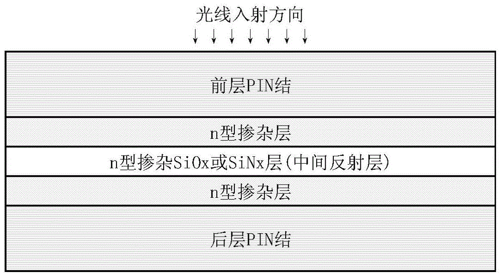
However, there are many problems caused by an overly thick intermediate layer in the single-layer design: (1) The intermediate reflective layer adjusts the refractive index by introducing oxygen elements, and the conductivity of the thick single-layer structure oxide film itself is not good, which is not conducive to the further improvement of battery efficiency. (2) The middle layer is usually placed in the n-type layer of the front PIN junction, and the single-layer structure will weaken the built-in electric field inside the battery, resulting in a loss of open circuit voltage; (3) There is only one selective reflection in the single-layer structure interface, and there are multiple reflective interfaces in the multilayer composite structure, which is more conducive to improving the selective reflection of light, so that short-wave light can be reflected more effectively and absorbed by the front battery

Method used


Image

  • Composite intermediate reflective layer for battery and multi-junction multi-stacked silicon-based thin film battery
  • Composite intermediate reflective layer for battery and multi-junction multi-stacked silicon-based thin film battery
  • Composite intermediate reflective layer for battery and multi-junction multi-stacked silicon-based thin film battery

Examples


Embodiment Construction

[0046] Below in conjunction with embodiment the present invention will be further described.

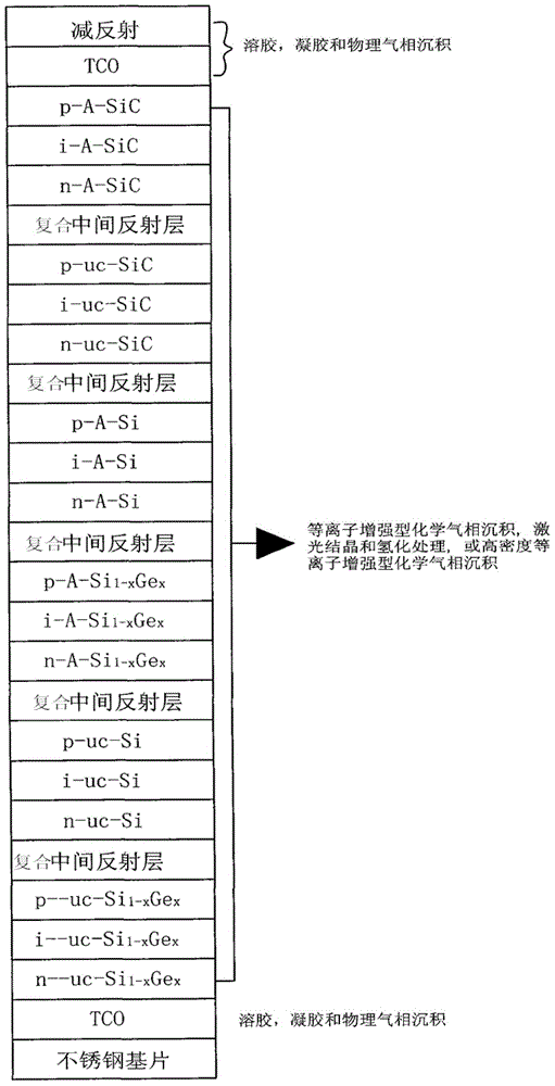
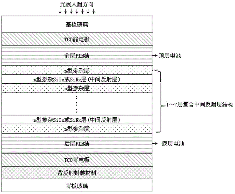
[0047] In the actual case of amorphous silicon / microcrystalline silicon double-junction laminated cells, high-efficiency silicon-based thin-film solar cells are prepared by applying the design structure of the composite intermediate reflective layer of the present invention, wherein two-layer and three-layer intermediate reflective layer structures are designed respectively , refer to attached Figure 4 , 5 :

[0048] (1) 2-layer intermediate reflective layer composite structure: glass substrate / TCO front electrode / p-A-Si / i-A-

[0049] Si / n-A-Si / n-μc-Si / intermediate reflection layer / n-μc-Si / intermediate reflection layer / n-μc-Si / p-μc-Si / i-μc-Si:H / n-μc- Si / TCO back electrode / encapsulation material (and back reflection layer) / glass backplane;

[0050] (2) 3-layer intermediate reflective layer composite structure: glass substrate / TCO front electrode / p-A-Si / i-A-Si / n-A-Si / n-μc-Si / inter...


PUM


Abstract

The invention discloses a compound middle reflecting layer for a battery and a multi-junction multi-lamination silicon-based thin-film battery. The compound middle reflecting layer comprises at least one middle reflecting layer, the layer in front of the each middle reflecting layer and the layer on back of the corresponding middle reflecting layer are both n-type adulteration layer without oxygen or nitrogen. The middle reflecting layer is n-type doped SiOx or SiNx. According to the compound middle reflecting layer for the battery, the refractive index can be flexibly adjusted through the oxidation or nitridation proportion, so that the selective reflection requirements for different wavebands of different film layers in the multi-junction multi-lamination thin-film solar batteries are met. Needed materials are all silicon-based thin-film mainstream materials, and the manufacturing technology is compatible with the large-scale industrialized manufacturing technology. Compared with batteries without the middle reflecting layer structure, the battery with the multi-junction multi-lamination silicon-based thin-film battery has the advantage that battery efficiency is improved by more than 10 %.

Description

technical field [0001] The invention relates to a thin-film solar battery structure with a compound intermediate reflection layer structure, which can be conveniently applied to the manufacturing technology of large-scale industrialized silicon-based thin-film solar batteries. Background technique [0002] In 1994, the Swiss IMT team took the lead in proposing the design concept of amorphous / microcrystalline silicon stacked cells, and obtained cells with a conversion efficiency of 9.1%. Effective way to battery. However, this series stack structure faces a challenge, that is, due to the limitation of light-induced attenuation, the thickness of the a-Si battery must be appropriately thinned, and due to the thinner thickness, its current usually limits the current of the series device; in 1996, For the first time, Fischer D et al. proposed that adding a ZnO intermediate reflective layer to the laminated battery can significantly improve the quantum efficiency and short-circui...

Claims


Application Information

Patent Timeline
Patent Type & Authority Patents(China)
IPC IPC(8): H01L31/054H01L31/056H01L31/076
CPCH01L31/0352H01L31/076Y02E10/52Y02E10/548
Inventor 谭学仕李廷凯张峰毛炳雪
Owner 湖南共创光伏科技有限公司
Learn More