

A steam cracking method
A technology of steam and cracking furnace, applied in the field of steam cracking, which can solve the problems of olefin coking and other problems, and achieve the effects of avoiding coking, stable operation and reducing coking
- Summary
- Abstract
- Description
- Claims
- Application Information
AI Technical Summary
Problems solved by technology
Method used
Image

Examples
Embodiment 1
[0075] This example is used to illustrate the steam cracking method provided by the present invention.
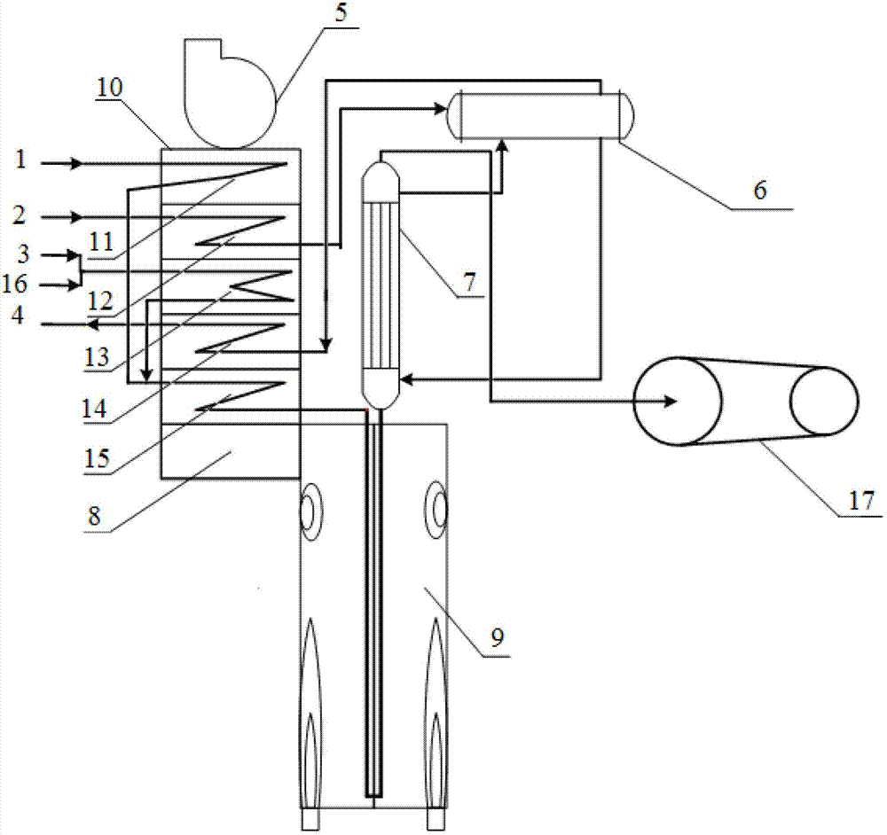
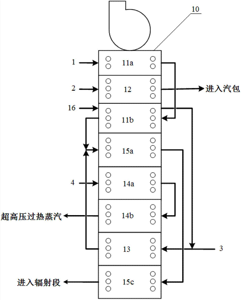
[0076] Using a convection section such as figure 2 The cracking furnace shown carries out the cracking reaction. The specific process includes:
[0077] Naphtha 1 at 60°C (relevant parameters are shown in Table 1) is preheated sequentially through the upper raw material preheating section 11a and the lower raw material preheating section 11b; the mixed olefins (composition is shown in Table 2) 16 are passed through the lower The raw material preheating section 11b is preheated, then mixed with steam, and the resulting mixture is heated through the dilution steam superheating section; then, the preheated naphtha is mixed with a mixture of mixed olefins and steam, and The obtained cracking raw material mixture is heated sequentially through the upper mixing heating section 15a and the lower mixing heating section 15c, and then enters the radiation section 9 for cracking re...
Embodiment 2
[0101] This example is used to illustrate the steam cracking method provided by the present invention.
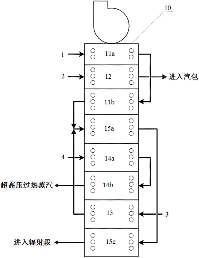
[0102] Carry out steam cracking according to the method for embodiment 1, difference is, as Figure 6 As shown, the mixed olefins (the composition is shown in Table 2) 16 are directly mixed with steam 3, and then the resulting mixture is preheated through the dilution steam superheating section 13, and the subsequent process is carried out. Among them, the process parameters of the convection section are shown in Table 8.
[0103] The pyrolysis product produced in the radiant section 9 is separated into high-pressure steam and cracked gas through the quenching heat exchanger 7, and the cracked gas enters the subsequent separation device through the cracked gas main pipe 17. Through the separation and analysis of the cracked gas, the composition of the cracked gas is shown in Table 9.
[0104] Table 8
[0105]
[0106] Table 9
[0107] components
weight% ...
Embodiment 3
[0111] This example is used to illustrate the steam cracking method provided by the present invention.
[0112] Carry out steam cracking according to the method for embodiment 2, difference is, the charging capacity of naphtha is 40860kg / h, and the charging capacity of mixed olefin is 4540kg / h, and the charging capacity of water vapor is 22700kg / h, and crossing temperature is 590°C, the outlet temperature (COT) of the radiation section 9 is 830°C, the residence time of the cracking raw material mixture in the radiation section 9 is about 0.23 seconds, and the process parameters of the convection section are shown in Table 10.
[0113] Table 10
[0114]
[0115] It can be seen from the data in Table 10 that the pressure drop of the dilution steam preheating section at the end of operation is 141.9kPa, and the pressure drop of the mixing heating section at the end of operation is 127.7kPa.
PUM
 Abstract
Description
Claims
Application Information