
Bearing-reclining-type mounted assembly-type wall

A prefabricated and wall technology, applied in the direction of walls, passive houses, building components, etc., can solve the problems of large space occupation, large amount of steel bars, and impact on durability, etc., to achieve convenient construction and installation, less steel consumption, and convenient increase. thick effect

Inactive Publication Date: 2014-02-19
吴淑环
View PDF4 Cites 11 Cited by
  • Summary
  • Abstract
  • Description
  • Claims
  • Application Information

AI Technical Summary

Problems solved by technology

At present, there is no prefabricated wall of light composite insulation board that can meet the regulations and engineering examples of limit state design, and the safety is poor.
There is also a thin iron sheet nailed on the edge of the prefabricated wall panel, and then the iron sheet is nailed to the main structure of the building to connect and install the prefabricated wall panel. How much tension can this connection bear? It is also unknown. It can only be used in low-rise buildings with little wind, and the corrosion resistance of the connection points is not good. The nails will corrode first, which will affect the durability.
In addition, dividing the wall panels into inner and outer layers and fixing them to the keel not only has more thermal bridges on the outside of the beams and columns, but also has much worse rigidity than combining two layers of wall panels into a prefabricated wall, and the force on the wall panels is not clear. and increase prefabrication and installation costs
[0014] 4. Some prefabricated wall panel templates for prefabricated walls require a large amount of investment, coupled with a large amount of land investment, which greatly increases the cost, making it difficult to implement prefabricated walls.
[0016] 1) The article "Connection Structure of Japanese Building Wall Panels" written by Yu Yan of Beijing Architectural Design and Research Institute shows that the seismic structure of Japan's slidable prefabricated walls is too complicated;
[0017] 2), as well as the architectural standard design atlas "Prefabricated Concrete External Wall Panels" 08SJ110-2, 08SG333, in which pages 16, 17, 32-35, 44-47 are external wall concrete hanging panels, which are slidable integral panels. The structure of the concrete wall panel is too complicated, it is difficult to process the prefabricated wall panel, it is difficult to install, the amount of steel bar is large, the number of installation parts is large, the weight is heavy, and the cost is high. It must be prefabricated on the platform, which takes up a lot of space and wastes precious land. Resources are currently only used in a few high-end projects, which is not conducive to the popularization of prefabricated walls and ensuring the safety of buildings against earthquakes and the safety of high-rise buildings against lateral movement
[0018] 6. When installing curtain wall decoration in high-rise buildings, especially when installing glass curtain wall decoration, under the action of wind load and horizontal earthquake, when the displacement angle between the main structure of the building occurs, the curtain wall is prone to extrusion damage, which is difficult to deal with
[0019] The above problems affect the durability and safety of buildings, affect building energy conservation and emission reduction, affect the reduction of global greenhouse gas emissions, affect the safety of buildings against earthquakes and high-rise buildings against lateral movement, and affect the process of housing industrialization

Method used


Image

  • Bearing-reclining-type mounted assembly-type wall
  • Bearing-reclining-type mounted assembly-type wall
  • Bearing-reclining-type mounted assembly-type wall

Examples


Embodiment approach 1

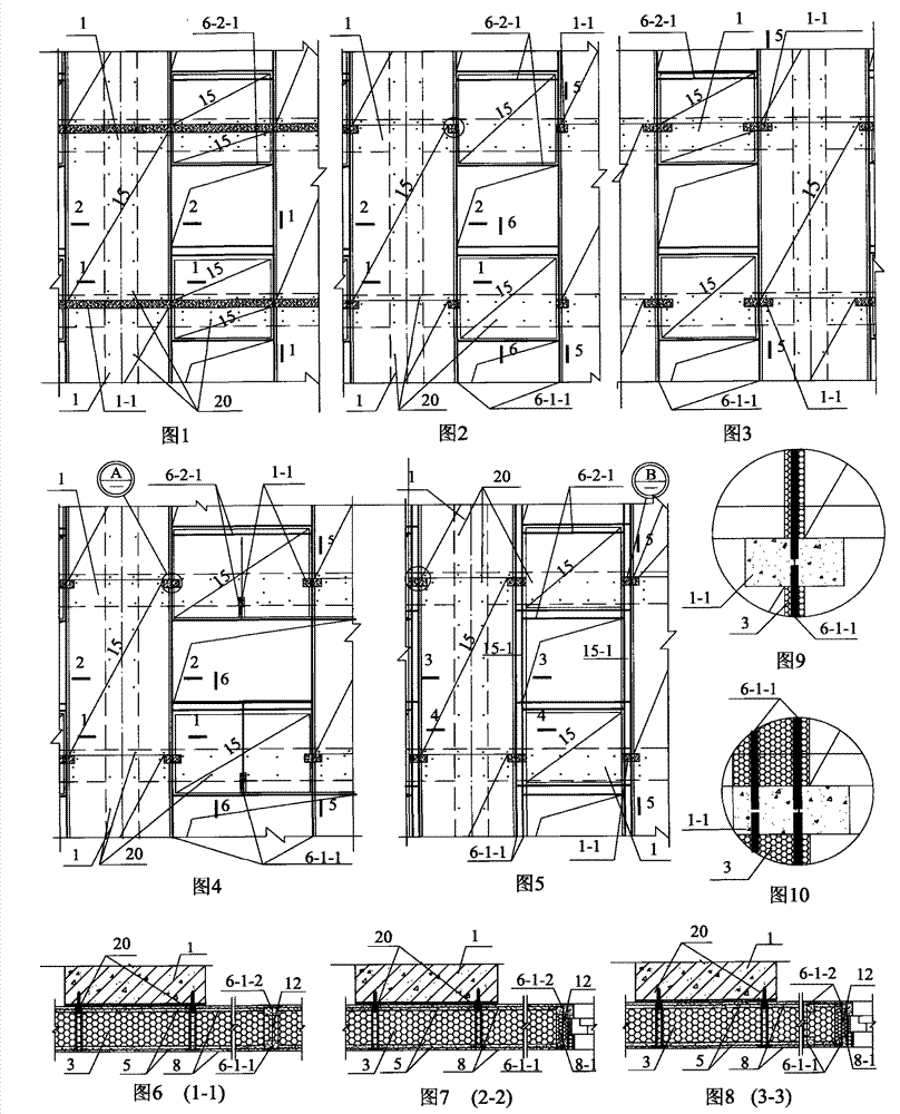
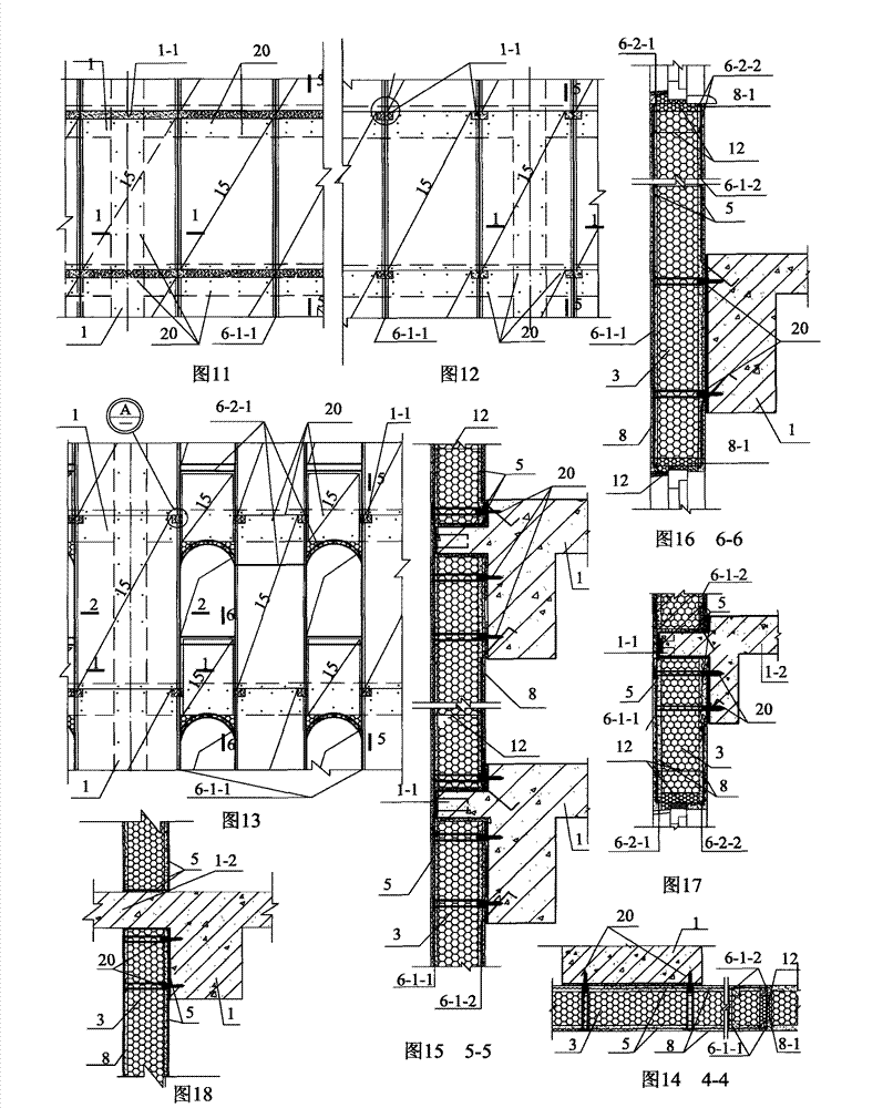
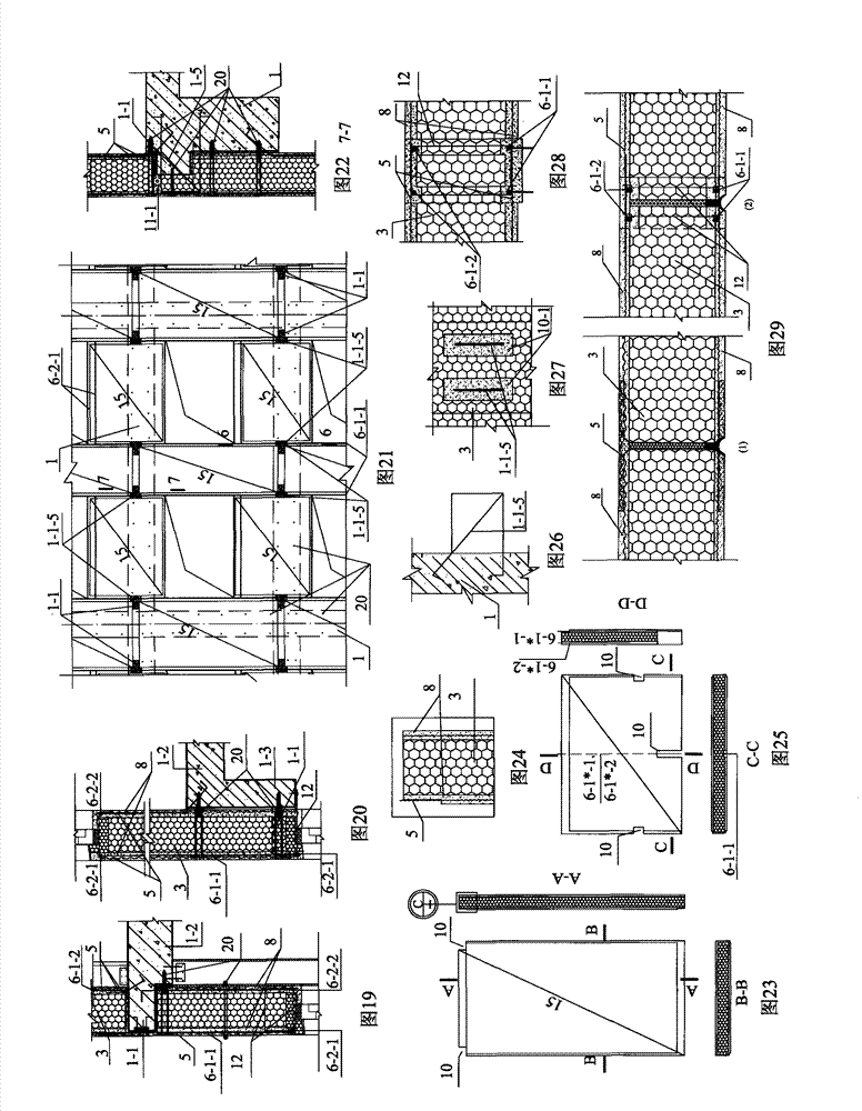
[0156] Implementation mode one: see Figure 1 to Figure 32 , Figure 41 , a prefabricated wall for supporting and leaning installation in this embodiment, which is composed of a main building structure 1, a prefabricated wall panel 15, or a prefabricated slat 15-1 (in the third embodiment, it needs to be installed Longitudinal steel bars, especially when double steel bars are installed, the double steel bars are installed on the prefabricated slats 15-1 for convenient construction); the main building structure 1 is a beam, slab, column wall and foundation, for example, the main building structure 1 is a concrete frame structure, steel concrete frame Structure, frame-shear structure, steel frame structure, steel pipe concrete structure, concrete and steel mixed frame structure, steel-wood frame structure, or bamboo frame, wood frame structure, shear wall structure, etc.;

[0157] On the outer side of the building main structure 1, there is a structural supporting part 1-1 supp...

Embodiment approach 2

[0180] Embodiment 2: The difference between this embodiment and Embodiment 1 is that the connection between the prefabricated wall and the main building structure 1 has the following methods, choose one of them, or 1), 2), and 3) to share:

[0181] 1), use the anchor bolt 20 to fix the prefabricated wallboard 15 or the prefabricated slat 15-1 with the side of the main building structure 1 or the additional abutment part 1-3; the anchor bolt 20 penetrates the prefabricated wallboard 15, the prefabricated strip The plate 15-1 is fixed to the side of the building main structure 1 or to the additional abutting piece 1-3;

[0182] 2) Bonding the prefabricated wall panels 15 and the prefabricated slats 15-1 to the sides of the beams, slabs, columns and shear walls of the main building structure 1, or / and to the sides of the additional abutting parts 1-3 with cementing materials;

[0183] When the prefabricated wallboard 15 and the prefabricated slat 15-1 are used as the formwork of ...

Embodiment approach 3

[0190] Embodiment 3: The difference between this embodiment and Embodiment 1 or 2 is that this embodiment increases steel bars 6 and steel hoops 12, and the steel bars 6 are located in the prefabricated wall protection layer 8; the steel bars 6 include longitudinal steel bars 6-1 and Horizontal reinforcing bar or curved reinforcing bar 6-2, or reinforcing bar 6 is the circular reinforcing bar (not shown in drawing) that is arranged around the door and window opening; The core layer at the seam is a bare board, and the longitudinal reinforcement is installed on site. It is more convenient to install one longitudinal reinforcement because there is less wet work.), or the longitudinal reinforcement 6-1 is located in the protective layer 8 of the prefabricated slab 15-1 (that is, Formwork prefabricated prefabricated slat 15-1, because there are many wet operations during the double reinforcement, it is more convenient to install longitudinal reinforcement 6-1 in the protective laye...


PUM


Abstract

The invention relates to assembly-type walls of buildings, in particular to a bearing-reclining-type mounted assembly-type wall, and aims at the problem of influences on energy conservation, housing industrialization and the like due to the fact that frame-structured walls has many thermal bridges and are poor in durability and complex in aseismatic structure. A structure I includes that structural bearing members bearing prefabricated wall plates are arranged on the outer sides of beam columns, and the prefabricated wall plates and the side faces of the beam columns are in bearing-reclining-type connection to form a common bearing-reclining-type assembly-type wall. A structure II includes that structural bearing members bearing prefabricated wall plates and prefabricated ribbon plates are arranged on the outer sides of beams, the prefabricated wall plates, the prefabricated ribbon plates and the side faces of the beam columns are in bearing-reclining-type connection, sliding components are mounted at horizontal seams of the prefabricated ribbon plates and the structural bearing members or beam plates, and when a main structure of a building is in inter-storey displacement, an assembly-type wall can be in horizontal displacement along with the beams or plates along sliding grooves to form a slidable bearing-reclining-type assembly-type wall. Energy-saving and heat-insulating effect of the wall is improved remarkably, the bearing-reclining-type mounted assembly-type wall is high in mounting speed, low in manufacturing cost, high in durability and good in aseismicity, and promoting of housing industrialization is facilitated.

Description

technical field [0001] The invention relates to a building wall body in construction, in particular to an assembled wall body supported and mounted against. Background technique [0002] The main problems existing in the installation of prefabricated walls with prefabricated wall panels are: [0003] 1. The energy-saving problem of building wall technology has not been completely solved. [0004] According to a report released by the United Nations in March 2007, the emission reduction effect of green buildings and building energy conservation is greater than all greenhouse gas emissions required in the "Kyoto Protocol", which is equivalent to three times the scheduled emission reductions of the "Kyoto Protocol". The state of building energy efficiency directly affects global warming, the melting of the North and South Poles, the melting of icebergs, rising sea levels, and the extinction of animals and plants. [0005] A report published by the World Bank warned: "Unless m...

Claims


Application Information

Patent Timeline
Patent Type & Authority Applications(China)
IPC IPC(8): E04B2/56E04B1/76E04B1/94
CPCY02A30/00Y02B30/90
Inventor 吴淑环
Owner 吴淑环
Learn More