Driving source for hydrogen thyratron control grid

A technology of hydrogen thyratron and control grid, which is applied in the field of driving source of hydrogen thyratron control grid, can solve the problems of damage to the main power controller, shorten the life of thyratron, and unsatisfactory output pulses, etc. The effect of weight, suppression of high-frequency electromagnetic interference, and smooth pulse

Inactive Publication Date: 2014-02-19
SUZHOU POWER COPPER LASER
View PDF4 Cites 4 Cited by
  • Summary
  • Abstract
  • Description
  • Claims
  • Application Information

AI Technical Summary

Problems solved by technology

The positive trigger pulse is directly added to the control grid G ​​by the output of the DC power supply C through the isolation pulse transformer. The tube is connected, shortening the life of the thyratron, and easily causing damage to the main power controller, etc.

Method used


Image

  • Driving source for hydrogen thyratron control grid
  • Driving source for hydrogen thyratron control grid

Examples


Embodiment Construction

[0026] The present invention will be further described below in conjunction with the embodiments and accompanying drawings, but the protection scope of the present invention should not be limited thereby.

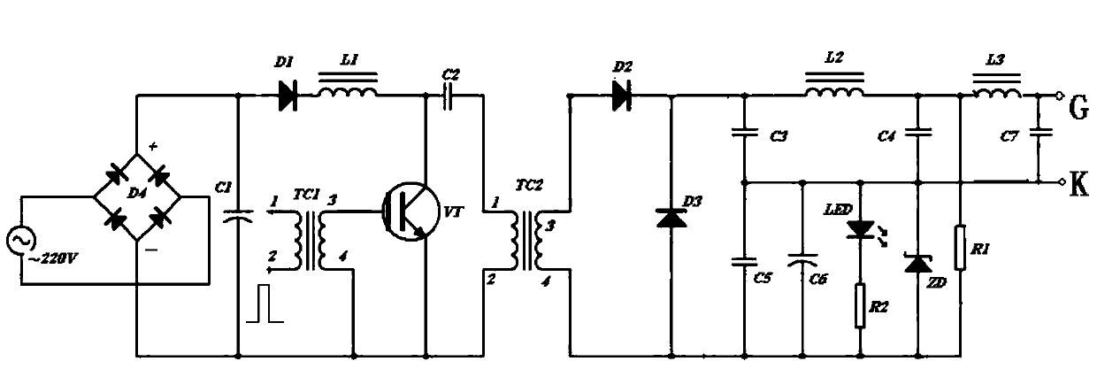
[0027] see first figure 2 , figure 2 It is the driving source circuit diagram of the hydrogen thyratron control grid of the present invention. It can be seen from the figure that the driving source of the hydrogen thyratron control grid of the present invention is only powered by single-phase ~ 220V, including pulse transformer TC2, The primary of the pulse transformer TC2 is provided with a pulse forming circuit, and the secondary of the pulse transformer TC2 is provided with a negative bias generating circuit, a magnetic pulse compression circuit and an L-C low-pass matching circuit.

[0028] The pulse forming circuit includes single-phase ~ 220V power supply, bridge pile D4, filter capacitor C1, isolation diode D1, charging inductor L1, energy storage capacitor C2, sw...


PUM


Abstract

The invention provides a driving source for a hydrogen thyratron control grid. The power of the driving source is supplied by a single-phase 220V power source. The driving source comprises a pulse transformer, wherein a pulse formation circuit is arranged at the primary level of the pulse transformer, and a negative bias generation circuit, a magnetic pulse compression circuit and an L-C low-pass matching circuit are arranged at the secondary level of the pulse transformer. According to the hydrogen thyratron control grid, the weight is reduced, the size is also reduced, and therefore integration of the driving source is facilitated; a hydrogen thyratron switch can be restrained from causing high frequency electromagnetic interference, connection of a hydrogen thyratron is avoided, the hydrogen thyratron is protected, and the service life of the hydrogen thyratron is prolonged; it can be ensured that the hydrogen thyratron works in an optimal state with low latency, low jitter, low drifting and high repetition frequency.

Description

technical field [0001] The invention relates to a hydrogen thyratron, in particular to a driving source for a hydrogen thyratron control grid. Background technique [0002] Hydrogen thyratrons feature low time jitter, low anode ignition delay time, low anode ignition delay time drift and high anode pulse current rise rate. It can be used in military, scientific research, medical fields and civilian high-tech products, including radar, laser, electron accelerator, and pulse modulator as a high-power switch with high pulse repetition frequency and fast rising edge pulse. [0003] The typical working circuit of a hydrogen thyratron is as follows: figure 1 shown, from figure 1 It can be seen from the figure that the hydrogen thyratron control grid needs dual power supplies: DC power supply B and DC power supply C. In addition to a positive trigger pulse to start the ignition, in order to shorten the capacitance elimination time and increase the repetition frequency of work, a ...

Claims


Application Information

Patent Timeline
Patent Type & Authority Applications(China)
IPC IPC(8): H03K17/687
Inventor 丁悦黄加新赵传奇姜阅清
Owner SUZHOU POWER COPPER LASER
Why Eureka
Try Eureka