Method and structure for winding wire of high-frequency transformer

A high-frequency transformer and winding technology, applied in the field of transformers, can solve the problems of poor tightness and flatness of high-frequency transformers, difficult to control, unstable winding voltage, etc.

Active Publication Date: 2014-02-26
FOSHAN OULI ELECTRONICS
View PDF4 Cites 2 Cited by
  • Summary
  • Abstract
  • Description
  • Claims
  • Application Information

AI Technical Summary

Problems solved by technology

[0003] There are many winding methods for existing high-frequency transformers, but the compactness and flatness of the high-frequency transformer obtained by using the existing winding methods for high-frequency transformers are poor, and the coupling between windings of high-frequency transformers is poor. As a result, when applied to the circuit, the winding voltage is prone to instability, which is difficult to control

Method used


Image

  • Method and structure for winding wire of high-frequency transformer
  • Method and structure for winding wire of high-frequency transformer

Examples


Embodiment 1

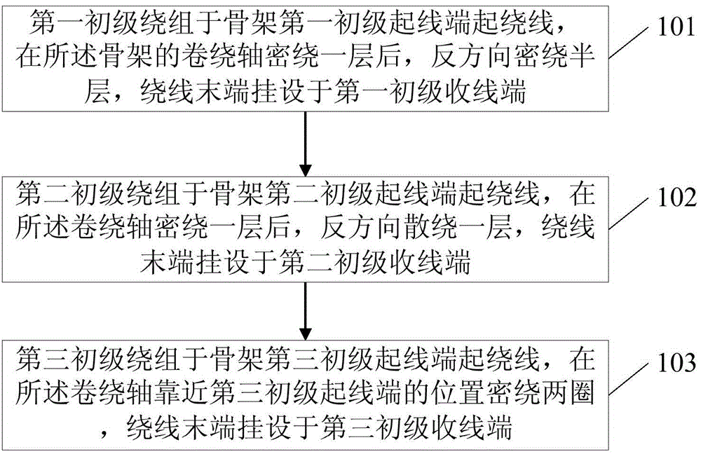
[0016] figure 1 It is a flow chart of the high frequency transformer winding method provided by the first embodiment of the present invention. like figure 1 As shown, the method provided by the embodiment of the present invention includes:

[0017] Step 101, the first primary winding is wound at the first primary starting end of the frame, after the winding axis of the frame is tightly wound for one layer, the opposite direction is tightly wound for half a layer, and the end of the winding is hung on the first primary winding end. end of line.

[0018] Step 102, the second primary winding is wound at the second primary starting end of the skeleton, after the winding shaft is tightly wound for one layer, the winding shaft is wound one layer in the opposite direction, and the end of the winding is hung on the second primary winding end .

[0019] Step 103, the third primary winding is wound at the third primary start-up end of the skeleton, close-wound two turns at the posit...

Embodiment 2

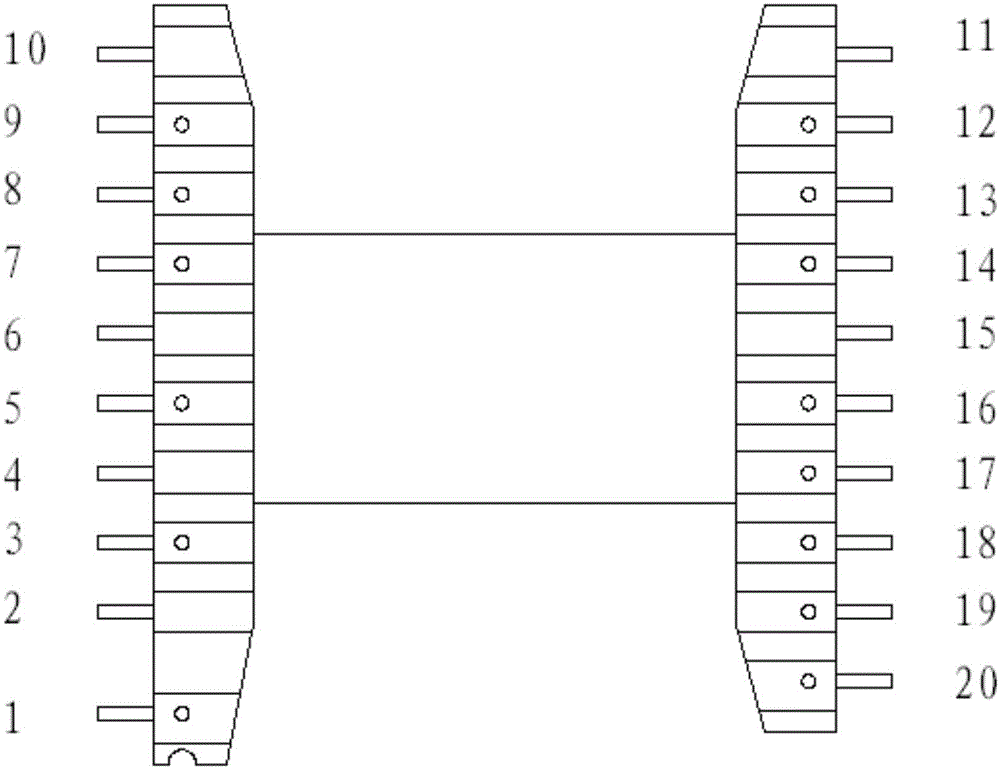
[0027] figure 2 It is a schematic diagram of the winding method of the high-frequency transformer provided by the second embodiment of the present invention. This embodiment provides a preferred embodiment based on the first embodiment. like figure 2 As shown, the method provided by the embodiment of the present invention includes:

[0028] The first primary winding starts 20 strands of enamelled copper wire at the first primary starting end 5 of the skeleton, and the 20 strands of enamelled copper wire form a counterclockwise twisted winding, after the winding shaft of the skeleton is tightly wound for one layer Add a layer of insulating tape, and wind half a layer in the opposite direction, and the end of the winding is hung on the end 7 of the first primary take-up end.

[0029] The first secondary winding starts with 27 strands of enamelled copper wires at the first secondary starting ends 12, 13 and 14 of the skeleton, and divides them into counterclockwise twisted w...


PUM


Abstract

The invention discloses a method and structure for winding a wire of a high-frequency transformer. The method includes the steps of firstly, starting to wind the wire at a first primary winding start end of a framework through a first primary winding, backward and densely winding the wire on a winding shaft by a half layer after densely winding the wire on the winding shaft of the framework by a whole layer, and allowing the tail end of the wire to be hung at a first primary winding stop end; secondly, starting to wind the wire at a second primary winding start end of the framework through a second primary winding, backward and loosely winding the wire on the winding shaft by a layer after densely winding the wire on the winding shaft by a layer, and allowing the tail end of the wire to be hung at a second primary winding stop end; thirdly, starting to wind the wire at a third primary winding start end of the framework through a third primary winding, densely winding the wire on the position, close to the third primary winding start end, of the winding shaft by two circles, and allowing the tail end of the wire to be hung at a third primary winding stop end. According to the method and structure of winding the wire of the high-frequency transformer, by changing the winding method of the primary windings, the phenomenon that all the windings are not stable in voltage can be eliminated, and performance of the high-frequency transformer can be improved.

Description

technical field [0001] The invention relates to the technical field of transformers, in particular to a winding method and structure of a high-frequency transformer. Background technique [0002] High-frequency transformer is a power transformer whose operating frequency exceeds the intermediate frequency. It is mainly used as a high-frequency switching power transformer in high-frequency switching power supplies, and can also be used as a high-frequency inverter power transformer in high-frequency inverter power supplies and high-frequency inverter welding machines. . A high frequency transformer includes a skeleton, a magnetic core, a primary winding and a secondary winding. The magnetic core is set on the bobbin, and the primary winding and the secondary winding are both wound on the magnetic core. The frame includes the winding shaft, the connecting terminal of the primary winding and the connecting terminal of the secondary winding. The connecting terminal can be used ...

Claims


Application Information

Patent Timeline
Patent Type & Authority Applications(China)
IPC IPC(8): H01F27/30H01F41/06
Inventor 赵春卫
Owner FOSHAN OULI ELECTRONICS
Why Eureka
Try Eureka