An on-site calibration device for an optical fiber current sensor and its application method

A fiber optic current and on-site calibration technology, which is applied to measuring devices, digital measurement technology for measurement, instruments, etc., can solve the long-term stability, reliability and safety indicators that are difficult to meet industry requirements, and the measurement accuracy is difficult to reach 0.05 %, the accuracy of the current detection sensor is out of tolerance, etc., to achieve the effect of convenient and safe installation, improving detection sensitivity and reducing transmission error

Active Publication Date: 2016-04-13
XUNDI SCI & TECH HUBEI PROV
View PDF8 Cites 0 Cited by
  • Summary
  • Abstract
  • Description
  • Claims
  • Application Information

AI Technical Summary

Problems solved by technology

[0009] The purpose of the present invention is to provide an on-site verification device for optical fiber current sensors to solve the problem that the accuracy of current detection sensors is prone to out-of-tolerance situations in the electrolysis industries such as chemical industry or non-ferrous metals, especially in long-term on-site operations Under the circumstances, the existing current detection devices are generally affected by many factors such as on-site environmental temperature, time, location and external magnetic field, and its long-term stability, reliability and safety indicators are difficult to meet the industry requirements. , and at the same time solve the blocking problem of the existing modulator due to the cross-coupling of the weak electrical signal, such as the blocking problem of the DC small current measurement, and the method of increasing the electrical signal jitter or performing random modulation can only reduce the blocking phenomenon, but cannot fundamentally Eliminate it, which leads to the problem that the overall measurement accuracy is difficult to reach 0.05%; realize fast, economical and accurate error detection and value transmission of the long-term DC high-current sensor on site, and improve the measurement accuracy of the current detection device. Reduce its size, improve its installation convenience, and meet the needs of safe and stable operation of the power supply system

Method used


Image

  • An on-site calibration device for an optical fiber current sensor and its application method
  • An on-site calibration device for an optical fiber current sensor and its application method
  • An on-site calibration device for an optical fiber current sensor and its application method

Examples


Embodiment 1

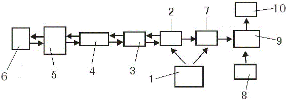
[0043] An on-site verification device for an optical fiber current sensor, comprising a connected optical fiber current detection sensing module and an optical fiber current detection processing and display module 9, wherein the optical fiber current detection sensing module modulates a reference light and then compares it with the detected signal Closed-loop control mode in which comparison processing is performed to obtain verification results.

Embodiment 2

[0045] Such as figure 1As shown, an on-site verification device for a fiber optic current sensor is the same as in Embodiment 1, except that the fiber optic current detection sensing module consists of a light source 1, a linear polarizer, a polarization separator, a modulator 2, and a transmission fiber 3 , 1 / 4 wavelength filter 4, optical fiber sensing head 5, mirror 6 and photodetector 7; the optical fiber sensing head 5 and the sensor 8 to be verified are surrounded on the same conductive bus; the light source 1 The modulator 2 is connected to the modulator 2 through a linear polarizer and a polarization splitter, and the modulator 2 is connected to the transmission fiber 3, and the transmission fiber 3 is connected to the 1 / 4 wavelength filter 4, and the 1 / 4 The wavelength filter 4 is connected with the optical fiber sensing head 5 again, and the optical fiber sensing head 5 is connected with the radiation mirror; the light source 1 is also connected with the photodetecto...

Embodiment 3

[0047] Such as figure 1 and image 3 As shown, an on-site verification device for an optical fiber current sensor is the same as that in Embodiment 2, except that the modulation signal of the modulator 2 is separated from the closed-loop signal and applied to the two arms of the modulator 2 respectively.


PUM


Abstract

The invention relates to an on-site verification apparatus for an optical fiber current sensor, a usage method of the on-site verification apparatus and application of the on-site verification apparatus. The on-site verification apparatus for the optical fiber current sensor includes an optical fiber current detection sensing module and an optical fiber current detection processing and display module. The optical fiber current detection sensing module is composed of a light source, a linear polariscope, a polarization separator, a modulator, a transmission optical fiber, a 1 / 4 wavelength filter, an optical fiber sensing head, a reflector and a photoelectric detector. Proceeding from installation and debugging of the optical fiber current detection sensing module, the optical fiber current sensor on-site verification apparatus has reasonable control steps, is easy to operate, and can carry out efficient, economic and accurate error detection and quantity transmission on a DC heavy current sensor working on site for a long time; the optical fiber current sensor on-site verification apparatus is suitable for detecting and verifying a current detection sensor working on site for a long time in fields of electrolytic aluminum, electrolytic copper, electric smelting, electroplate and other electrochemical engineering; the on-site verification apparatus for the optical fiber current sensor is good in safety performance, large in measuring dynamic scope, high in frequency response degree, small in size and light in weight; and by adopting the on-site verification apparatus for the optical fiber current sensor, the measuring precision of a current detection apparatus can be raised, and needs of safety and stabilization of a power supply system are met.

Description

technical field [0001] The invention belongs to the technical field of measuring electric variables by optical instruments, and relates to a device for measuring current by using a light modulation method and its use method and application, in particular to a convenient and accurate error detection and measurement method for a current detection sensor that has been working for a long time on site. An on-site verification device for an optical fiber current sensor for value transmission, a method of use and an application thereof. Background technique [0002] In electrolysis industries such as chemical industry or non-ferrous metals, DC large current sensors have been widely used, which play a role in measuring and controlling DC large current in the production process. Because the production process of the industry has the characteristics of long-term and continuous, many DC high-current sensors generally have the problem of out-of-tolerance accuracy due to the influence of...

Claims


Application Information

Patent Timeline
Patent Type & Authority Patents(China)
IPC IPC(8): G01R35/00G01R19/25
Inventor 龚文俊裴朝阳李纯朴李耿高立节
Owner XUNDI SCI & TECH HUBEI PROV
Why Eureka
Try Eureka