
A kind of magnesium alloy anti-gravity casting device and method thereof

A technology of anti-gravity casting and magnesium alloys, applied in the field of casting, can solve the problems of easy combustion or oxidation of magnesium alloys, and achieve the effects of preventing oxidation slag inclusion defects, good performance, and improving surface quality and internal structure.

Inactive Publication Date: 2015-08-05
HENAN POLYTECHNIC UNIV
View PDF7 Cites 0 Cited by
  • Summary
  • Abstract
  • Description
  • Claims
  • Application Information

AI Technical Summary

Problems solved by technology

[0007] The technical problem to be solved by the present invention is: to provide a magnesium alloy anti-gravity casting device to overcome the technical problem in the prior art that the magnesium alloy is prone to combustion or oxidation during the pouring process; and to provide a casting device using the device method

Method used


Image

  • A kind of magnesium alloy anti-gravity casting device and method thereof
  • A kind of magnesium alloy anti-gravity casting device and method thereof
  • A kind of magnesium alloy anti-gravity casting device and method thereof

Examples


Embodiment 1

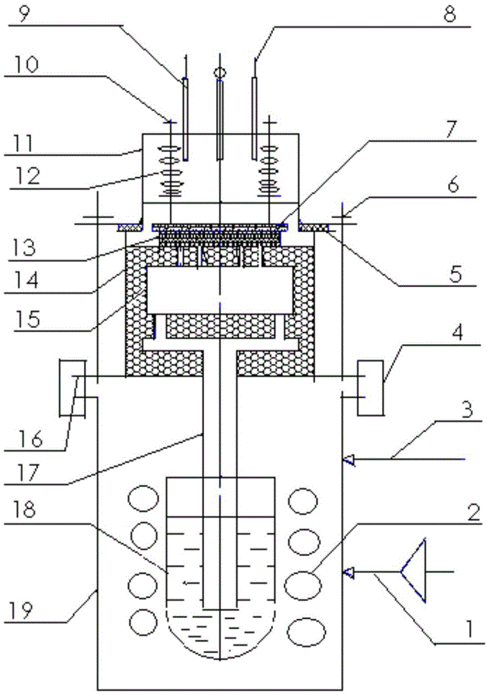
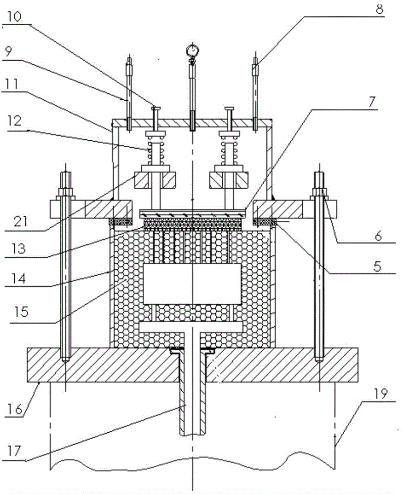
[0036] Such as figure 1As shown, this embodiment describes a magnesium alloy anti-gravity casting device, which includes: a melting furnace 2 and a crucible 18 built in a lower tank 19 , and the upper part of the lower tank 19 is isolated from the outside by a sealing cover 16 . In order to prevent the magnesium alloy melt from burning with oxygen, between the melting furnace 2 and the sealing cover plate 16 , the lower tank 19 is connected to the first protective gas pipeline 3 . In this way, the mixed gas of 1-10% sulfur hexafluoride and 90-99% argon injected through the first shielding gas pipeline 3, the sulfur hexafluoride with a larger proportion can float on the magnesium alloy melt, and react with the magnesium alloy The melt reacts to form a surface film with different protective effects on the surface of the magnesium alloy melt. The surface film is dense, which can not only isolate the magnesium alloy melt from the air, prevent the reaction from continuing, but also...

Embodiment 2

[0045] This embodiment describes a casting method using the device described in the above embodiments, the method includes the following steps:

[0046] Step 1. Put the magnesium alloy into a melting furnace at 730° C. to 820° C. for smelting and removing slag, and at the same time, heat the gypsum mold at 200° C. to 400° C. ;

[0047] Step 2. Put the molten magnesium alloy after smelting and deslagging into the crucible, seal the lower tank with a sealing cover, seal the contact surface between the riser and the sealing cover with asbestos, and lock the The sealing cover plate is locked with the lower tank.

[0048] Step 3. Place the heated plaster mold directly on the sealing cover, align the gate with the upper port of the riser, and use asbestos to seal the plaster mold, and then turn the negative pressure The gas protection box is directly placed on the plaster mold and fixedly connected with the sealing cover plate.

[0049] Step 4, using a mixed gas of 1-10% sulfur h...


PUM

PropertyMeasurementUnit
tensile propertiesaaaaaaaaaa
thicknessaaaaaaaaaa
diameteraaaaaaaaaa

Abstract

The invention discloses a magnesium alloy counter-gravity casting device. A melting furnace 2 and a crucible 18 are arranged in a lower tank 19; the upper part of the lower tank 19 is isolated from outside through a sealing cover plate 16; the lower tank 19 is connected to a first protective gas pipeline 3 between the melting furnace 2 and the sealing cover plate 16; the middle lower part of the lower tank 19 is connected to a pressing device 1; a negative pressure gas protection box 11 is connected to a second protective gas pipeline 8 and a negative pressure pipeline 9. The invention also discloses a method for casting with the device. Through the magnesium alloy counter-gravity casting device, large, complex and thin-wall magnesium alloy castings can be produced; the castings are high in surface quality and safety, and the production requirement can be met; the magnesium alloy counter-gravity casting device is simple to manufacture, applicable to scale production of magnesium alloys and high in production efficiency.

Description

technical field [0001] The invention relates to the technical field of casting, in particular to a magnesium alloy anti-gravity casting device and a method thereof. Background technique [0002] Magnesium alloy has low density and excellent performance. As an important structural material, it is widely used in aviation, aerospace, national defense, automobile, electronic communication and other fields. At present, the urgent need for weight reduction in my country's aviation, aerospace, and national defense fields provides opportunities and challenges for the development and application of new materials and processes for magnesium alloys. At present, one of the main factors limiting the wide application of magnesium alloy castings is the difficulty in casting magnesium alloy castings, especially for large, complex, thin-walled magnesium alloy castings, it is currently difficult to produce castings that meet the needs. One of the difficulties in casting is that there is no su...

Claims


Application Information

Patent Timeline
Patent Type & Authority Patents(China)
IPC IPC(8): B22D18/04B22D18/06
Inventor 历长云王狂飞许广涛张锦志周志杰米国发刘宝忠王有超
Owner HENAN POLYTECHNIC UNIV
Learn More