Non-linear chirp scaling imaging method

A technology of nonlinear frequency modulation and imaging method, which is applied in the direction of radio wave reflection/re-radiation, radio wave measurement system, and utilization of re-radiation, etc. It can solve the problems of not being able to adapt to changes in electromagnetic wave velocity and propagation direction, and achieve improved focusing performance. Effect

Inactive Publication Date: 2014-03-12
INST OF ELECTRONICS CHINESE ACAD OF SCI
View PDF0 Cites 11 Cited by
  • Summary
  • Abstract
  • Description
  • Claims
  • Application Information

AI Technical Summary

Problems solved by technology

[0005] In order to solve the problem that the traditional nonlinear CS algorithm is only suitable for single-layer medium imaging and cannot adapt to changes in electromagnetic wave velocity and propagation direction, the purpose of the present invention is to provide a modified nonlinear chirp scaling (CS) imaging method , it can automatically correct the refraction effect of electromagnetic waves at the interface of different media and the change of propagation speed of different media, and can effectively improve the focusing performance of scattering points

Method used


Image

  • Non-linear chirp scaling imaging method
  • Non-linear chirp scaling imaging method
  • Non-linear chirp scaling imaging method

Examples


Embodiment Construction

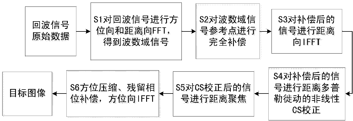
[0025] In order to make the object, technical solution and advantages of the present invention clearer, the present invention will be further explained in detail below in conjunction with the accompanying drawings and specific embodiments.

[0026] The software and hardware conditions required for the realization process from the original echo signal of the glacier thickness detection radar to the glacier thickness image detected by the radar are as follows:

[0027] Hardware: glacier thickness detection radar system, personal computer or server, USB flash drive;

[0028] Software: glacier thickness system control and data acquisition software, glacier thickness detection radar data processing program for nonlinear frequency modulation scale (CS) algorithm.

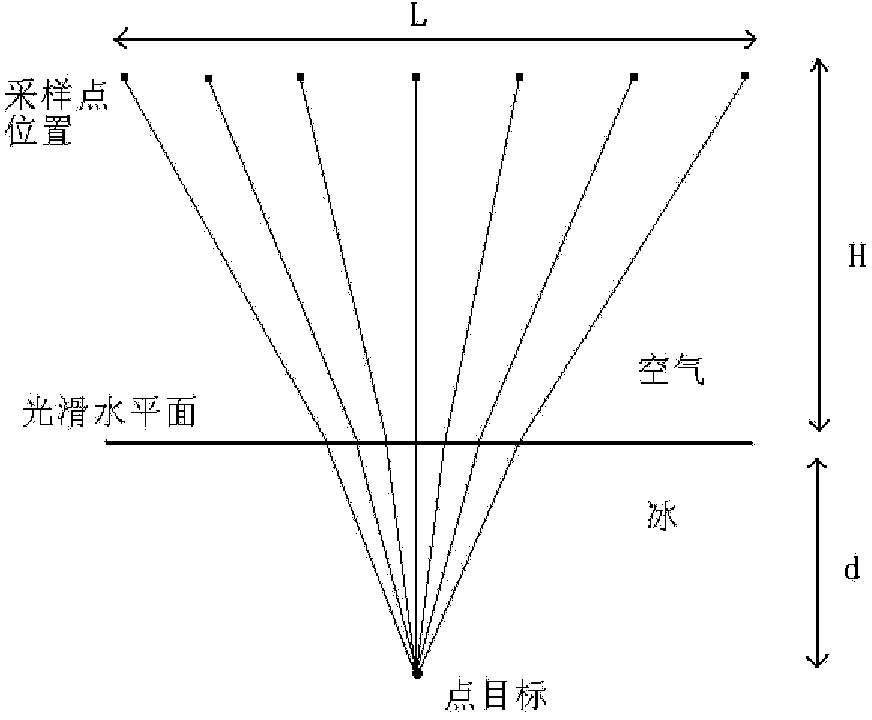
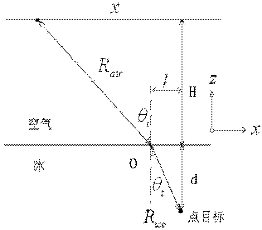
[0029] The invention is a two-layer medium imaging processing method involved in a low-frequency ultra-broadband glacier thickness detection radar aiming at a large processing angle, and the method is verified by actual m...


PUM


Abstract

The invention relates to a non-linear chirp scaling imaging method comprising the following steps: carrying out down-conversion, low pass filtering, distance and azimuth Fourier transform for glacier thickness detection radar echo signals, obtaining reference points of two dimension frequency domain echo signal in wavenumber domain, and carrying out phase compensation for the reference points; carrying out distance Fourier inversion to compensated wavenumber domain, multiplying distance migration of distance Doppler domain with a non-linear chirp scaling factor, carrying out non-linear chirp scaling correction, carrying out distance Fourier transform to distance Doppler domain signals correcting distance migration, obtaining a wavenumber domain signal of phase compensation and distance migration correction, carrying out distance focusing to the obtained wavenumber domain signal, obtaining the focused wavenumber domain signal, carrying out distance Fourier inversion to the focused wavenumber domain signal, carrying out azimuth compression and residual phase compensation to the distance Doppler domain signals, obtaining the distance Doppler domain signals after azimuth compression and residual phase compensation, carrying out azimuth Fourier inversion to the distance Doppler domain signals after the azimuth compression and residual phase compensation, thereby obtaining radar detected glacier thickness image.

Description

technical field [0001] The invention belongs to the technical field of radar imaging, and relates to a non-linear frequency modulation scale (CS) imaging method of a glacier thickness detection radar. Background technique [0002] Since the end of the last century, global warming has led to the melting of polar glaciers, which has caused sea levels to rise at a rate of 2 mm per year, threatening the living space of human beings. Because glaciers have the advantages of small attenuation of radio waves, good stratification and homogeneity of ice bodies, glacier detection using radar has been proved to be an effective technical means. Using the synthetic aperture method to complete the glacier thickness detection radar imaging processing can not only improve the signal-to-noise ratio, but also improve the azimuth resolution, and at the same time have the effect of clutter suppression, which has a wide range of applications in glacier thickness measurement. [0003] However, th...

Claims


Application Information

Patent Timeline
Patent Type & Authority Applications(China)
IPC IPC(8): G01S13/90G01S7/41
CPCG01S13/103G01S13/9011
Inventor 赵博王文鹏刘小军方广有
Owner INST OF ELECTRONICS CHINESE ACAD OF SCI
Why Eureka
Try Eureka