Gas protection non-oxidation quenching carburizing integrated furnace and quenching and carburizing method

A gas protection, non-oxidation technology, applied in the direction of quenching device, furnace, furnace type, etc., can solve the problems of waste of steel foil, easy deformation of muffle furnace, etc.

Inactive Publication Date: 2014-03-19
朱明耀
View PDF2 Cites 1 Cited by
  • Summary
  • Abstract
  • Description
  • Claims
  • Application Information

AI Technical Summary

Problems solved by technology

In the normal pressure quenching furnace, in order to prevent the oxidation reaction between the metal workpiece and the oxygen in the air during the high temperature heating stage, it is generally necessary to wrap the metal workpiece to be quenched with steel foil to isolate the metal workpiece

Method used


Image

  • Gas protection non-oxidation quenching carburizing integrated furnace and quenching and carburizing method

Examples


Embodiment 1

[0017] Embodiment 1: Gas protection non-oxidation quenching and carburizing integrated furnace and its quenching and carburizing method

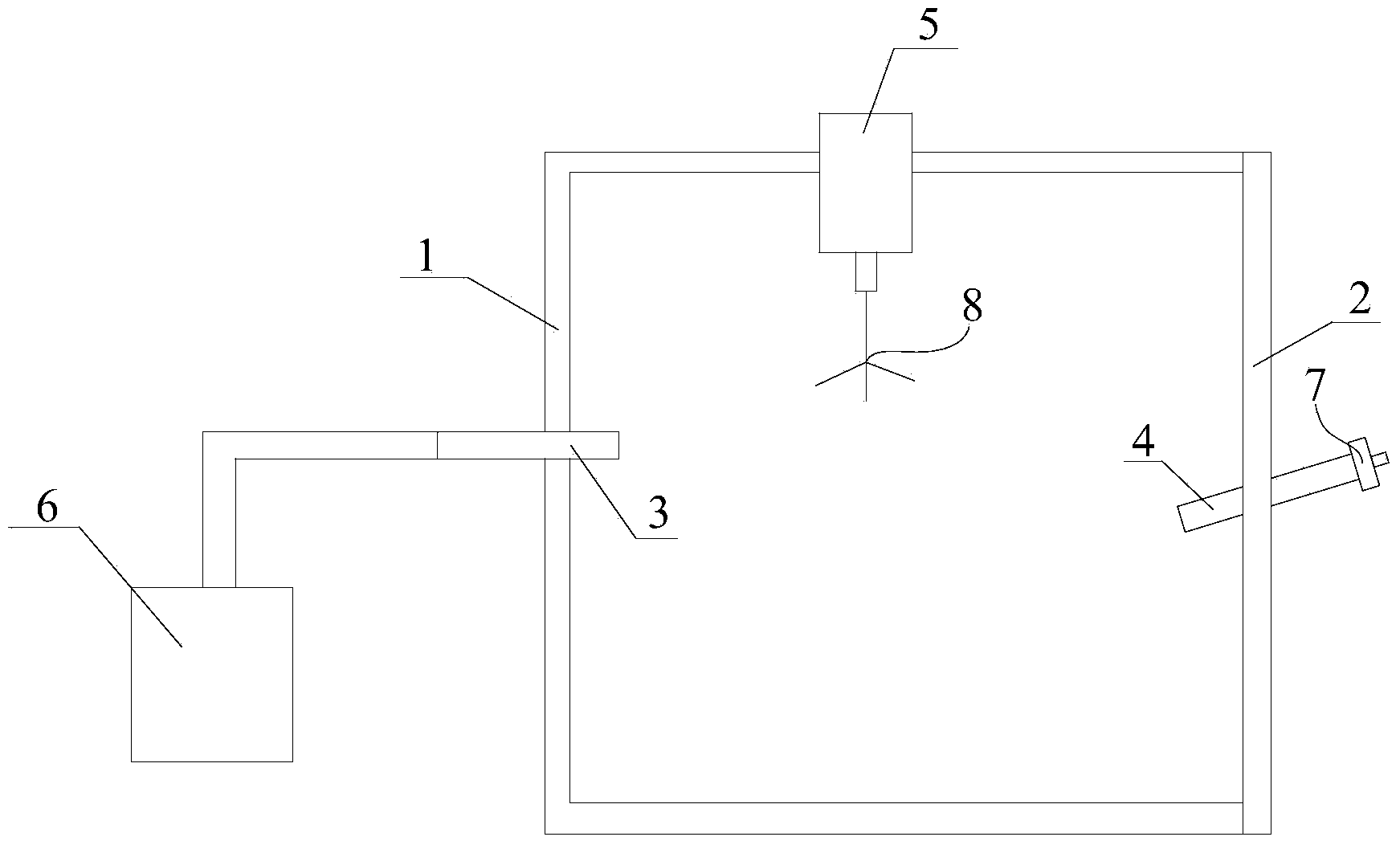
[0018] See attached figure 1 As shown, the gas-shielded non-oxidizing quenching and carburizing integrated furnace includes a heating chamber, which is composed of a closed space enclosed by a furnace body 1 and a furnace door 2; the furnace door 2 is provided with an exhaust pipe 4, The exhaust pipe 4 communicates with the heating chamber, the exhaust pipe 4 is provided with an ignition port 7; the heating chamber is provided with a silicon carbide rod; the furnace body 1 is provided with an air inlet pipe 3, and in this embodiment Among them, the intake pipe 4 communicates with the exhaust port of the ammonia cracking device 6 .

[0019] The heating chamber is lined with mullite brick insulation cotton.

[0020] The furnace body 1 is sealed with a water-cooled motor 5, and the rotor of the water-cooled motor 5 is connected to a stirring ...

Embodiment 2

[0022] Embodiment 2: Gas protection non-oxidation quenching carburizing integrated furnace and carburizing method

[0023] See attached figure 1 As shown, the gas protection non-oxidation quenching carburizing integrated furnace, the gas protection non-oxidizing quenching carburizing integrated furnace includes a heating chamber, the heating chamber is composed of a closed space enclosed by the furnace body 1 and the furnace door 2; The furnace door 2 is provided with an exhaust pipe 4, the exhaust pipe 4 communicates with the heating chamber, the exhaust pipe 4 is provided with an ignition port 7; the heating chamber is provided with a silicon carbide rod; the furnace body 1 is provided with an air inlet pipe 3, and in this embodiment, the air inlet pipe 3 communicates with the gas supply port of a liquefied gas supply device (not shown in the figure).

[0024] In the method of carburizing using a gas-protected non-oxidizing quenching and carburizing integrated furnace, firs...


PUM


Abstract

Provided are a gas protection non-oxidation quenching carburizing integrated furnace and a method. The integrated furnace comprises a heating chamber. The heating chamber is composed of an enclosed space formed through enclosure of a furnace body and a furnace door. A gas outlet pipe is arranged on the furnace body or the furnace door. The gas outlet pipe is communicated with the heating chamber. A lighting up tuyere is arranged on the gas outlet pipe. A silicon carbon rod is arranged in the heating chamber. A gas inlet pipe is arranged on the furnace body or the furnace door. The gas inlet of the gas inlet pipe is communicated with a gas outlet of an ammonia cracking device, or the gas inlet of the gas inlet pipe is communicated with a gas supply inlet of a liquefied gas supply device. The heating chamber is an enclosed space. When the furnace door is closed, external air cannot go into the heating chamber, and the air in the heating chamber is brought to the gas outlet pipe by the ammonia cracking gases or liquefied gases, and burnt at the lighting up tuyere, and therefore oxygen in the heating chamber is less and less, so when a metal workpiece is heated to a high temperature, no oxidation reaction is generated on the surface of the metal workpiece.

Description

technical field [0001] The invention relates to a gas-protected non-oxidation quenching and carburizing integrated furnace and a quenching and carburizing method thereof, and belongs to the technical field of heat treatment of metal workpieces. Background technique [0002] The metal heat treatment process is to heat the metal workpiece to an appropriate temperature and keep it for a period of time, and then immerse it in the quenching medium for rapid cooling. Commonly used quenching media are brine, water, mineral oil, air, etc. Quenching can improve the hardness and wear resistance of metal workpieces, so it is widely used in various tools, molds, measuring tools and parts that require surface wear resistance (such as gears, rolls, carburized parts, etc.). Through the combination of quenching and tempering at different temperatures, the strength, toughness and fatigue strength of the metal can be greatly improved, and the coordination between these properties (comprehens...

Claims


Application Information

Patent Timeline
IPC IPC(8): C21D1/62C21D1/74C21D9/00C23C8/20C23F17/00
Inventor 朱明耀
Owner 朱明耀
Why Eureka
Try Eureka