Biomass Horizontal Rotary Core Carbonization Furnace

A biomass and carbonization furnace technology, applied in fixed carbonization furnaces, etc., can solve the problems of low production capacity of a single machine, high processing cost, and large burning loss of fixed carbon, so as to promote balance and rapidity, and high C element content , the effect of reliable quality assurance

Active Publication Date: 2021-12-21
无锡光核新能源建设有限公司
View PDF15 Cites 0 Cited by
  • Summary
  • Abstract
  • Description
  • Claims
  • Application Information

AI Technical Summary

Problems solved by technology

[0002] At present, the mature biomass carbonization furnaces on the market are mainly vertical fixed bed carbonization furnaces and horizontal rotary kiln carbonization furnaces, both of which use oxygen-deficient combustion to release heat energy to pyrolyze biomass raw materials, and there is a loss of fixed carbon. Large amount, low carbon production rate, and the quality of charcoal products cannot be guaranteed; at the same time, the associated gas is a product of oxygen-deficient combustion, which contains a large amount of nitrogen brought in by air, so the gas production is large, the temperature and calorific value are low, and the precipitation Tar, the use value and process reliability have been reduced, this kind of tar is hazardous waste, the treatment cost is high, and it threatens the ecological environment and personal health and safety; Defects such as low comprehensive utilization efficiency of material raw materials and high power consumption
The existence of these problems seriously restricts the further development of the carbonization industry of biomass raw materials.

Method used


Image

  • Biomass Horizontal Rotary Core Carbonization Furnace
  • Biomass Horizontal Rotary Core Carbonization Furnace
  • Biomass Horizontal Rotary Core Carbonization Furnace

Examples


Embodiment Construction

[0018] The specific implementation manner of the present invention will be described below in conjunction with the accompanying drawings.

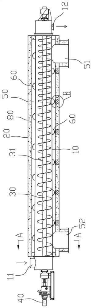
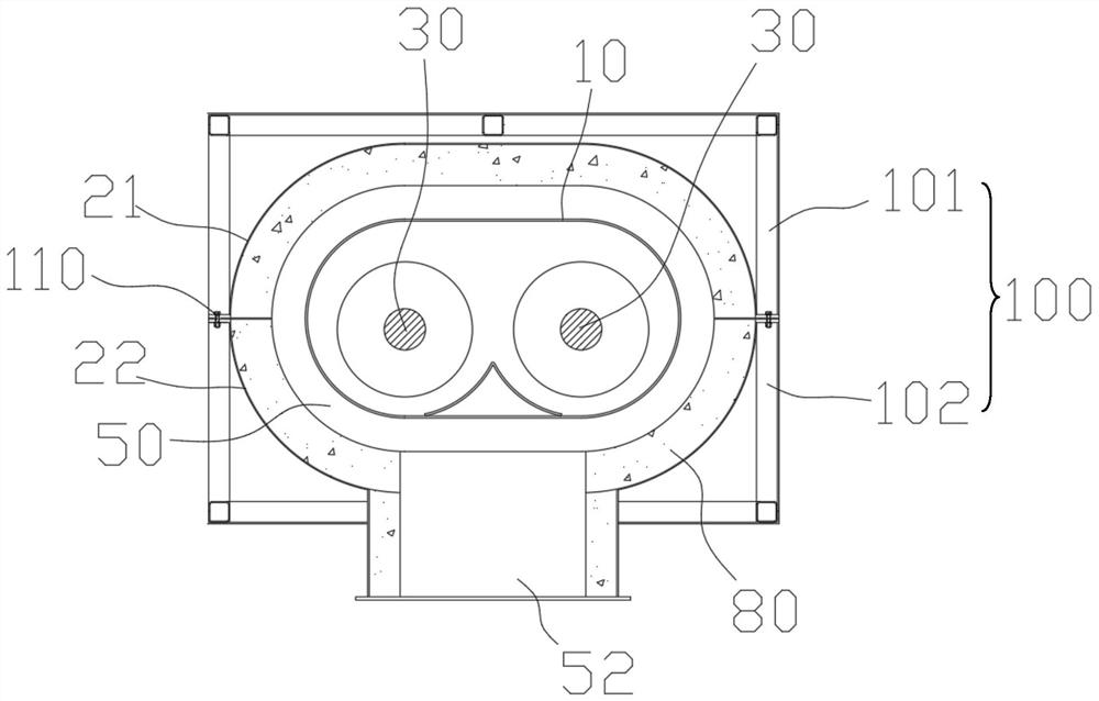
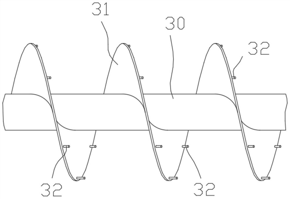
[0019] Such as Figure 1-4 As shown, the biomass horizontal rotary core carbonization furnace of this embodiment includes an inner cylinder 10 and an outer cylinder 20 sleeved outside the inner cylinder 10. The inner cylinder 10 is provided with a rotary core push twisting shaft 30, and the rotary core push twist There are helical blades 31 on the peripheral wall of the shaft 30. The front end of the rotary core push-twist shaft 30 hangs outside the inner cylinder 10 and is driven by the motor 40 to realize the rotation of the rotary core push-twist shaft 30. The front end and the rear of the inner cylinder 10 The ends are respectively suspended outside the outer cylinder 20, the front end of the inner cylinder 10 is provided with a raw material inlet 11, the rear end of the inner cylinder 10 is provided with a first outlet 12, and the out...


PUM


Abstract

The invention relates to the technical field of carbonization furnaces, in particular to a biomass horizontal rotary core carbonization furnace, wherein the inner cylinder is provided with a rotary core push twist shaft, and the outer peripheral wall of the rotary core push twist shaft has spiral blades, and the rotary core push twist shaft The front end of the twisted shaft hangs outside the inner cylinder and is driven by a motor to rotate. The front end and rear end of the inner cylinder respectively hang outside the outer cylinder. The front end of the inner cylinder is provided with a raw material inlet, and the rear end of the inner cylinder is provided with a first outlet. A heating chamber is enclosed between the inner cylinder and the outer cylinder. The rear end of the outer cylinder is provided with a heating medium inlet, and the front end of the outer cylinder is provided with a heating medium outlet. A plurality of stirring columns are vertically arranged on the spiral blades. There is a spiral deflector, the bottom of the spiral deflector is provided with a plurality of rolling support units, and the bottom of the spiral deflector forms a rollable support fit in the direction of the cylinder length through the rolling support units and the inner wall of the outer cylinder. The invention has the advantages of high raw material char formation rate, improved production efficiency, guaranteed charcoal product quality and long service life.

Description

technical field [0001] The invention relates to the technical field of carbonization furnaces, in particular to a biomass horizontal rotary core carbonization furnace. Background technique [0002] At present, the mature biomass carbonization furnaces in the market are mainly vertical fixed-bed carbonization furnaces and horizontal rotary kiln carbonization furnaces. Both of them use the heat energy released by hypoxic combustion to pyrolyze biomass raw materials, and there is a loss of fixed carbon. The amount of carbon is large, the carbon production rate is reduced, and the quality of carbon products cannot be guaranteed; at the same time, the associated gas is a product of oxygen-deficient combustion, which contains a large amount of nitrogen brought in by air, so the gas production is large, the temperature and calorific value are low, and the precipitation Tar, the use value and process reliability have been reduced, this kind of tar is hazardous waste, the treatment c...

Claims


Application Information

Patent Timeline
Patent Type & Authority Patents(China)
IPC IPC(8): C10B1/06
CPCC10B1/06
Inventor 蒋文年王伟陈弘刘建国汪关伟徐怡婷董俊男
Owner 无锡光核新能源建设有限公司
Why Eureka
Try Eureka