

Seawater desalinization method and seawater desalinization device
A seawater and freshwater technology, used in seawater treatment, general water supply conservation, heating water/sewage treatment, etc., can solve the problems of unsatisfactory freshwater quality, low thermal energy recycling, and high manufacturing and maintenance costs, and is conducive to energy exchange and consumption. The effect of low power consumption and saving installation cost
- Summary
- Abstract
- Description
- Claims
- Application Information
AI Technical Summary
Problems solved by technology
Method used
Image

Examples
Embodiment 1
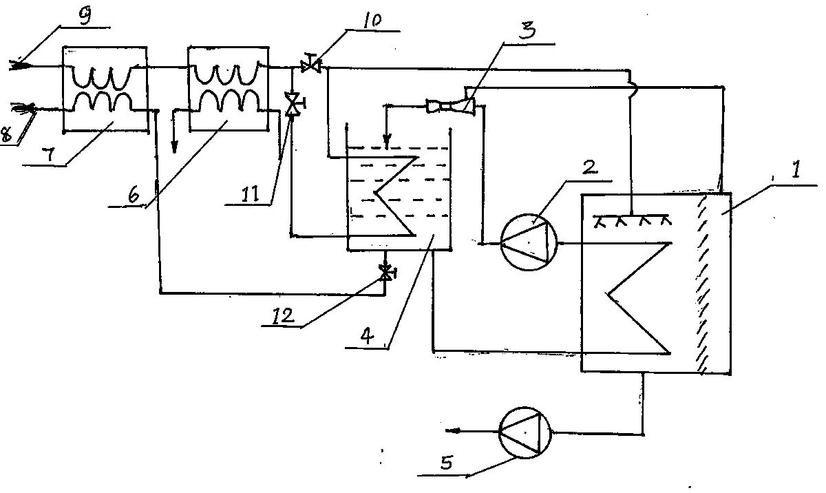
[0032] refer to figure 1 The seawater desalination device of this embodiment includes a first jet circulation pump 2, a first condensation ejector 3, a first fresh water circulation tank 4 and a first evaporator 1; the lower part of the first fresh water circulation tank 4 is connected to the first evaporator 1 through a pipeline. The inlet port of the first evaporator 1 is connected to each other, the outlet port of the first evaporator 1 is connected to the inlet port of the first jet circulation pump 2 through a pipeline, and the outlet port of the first jet circulation pump 2 is connected to the inlet port of the first condensing injector 3 through a pipeline, The outlet end of the first condensing injector 3 is provided with the pipeline that the nozzle extends into the first fresh water circulation tank 4, and the injection end interface of the first condensing injector 3 is connected to the vacuum chamber of the first evaporator 1 through the pipeline; A fresh water cir...
Embodiment 2
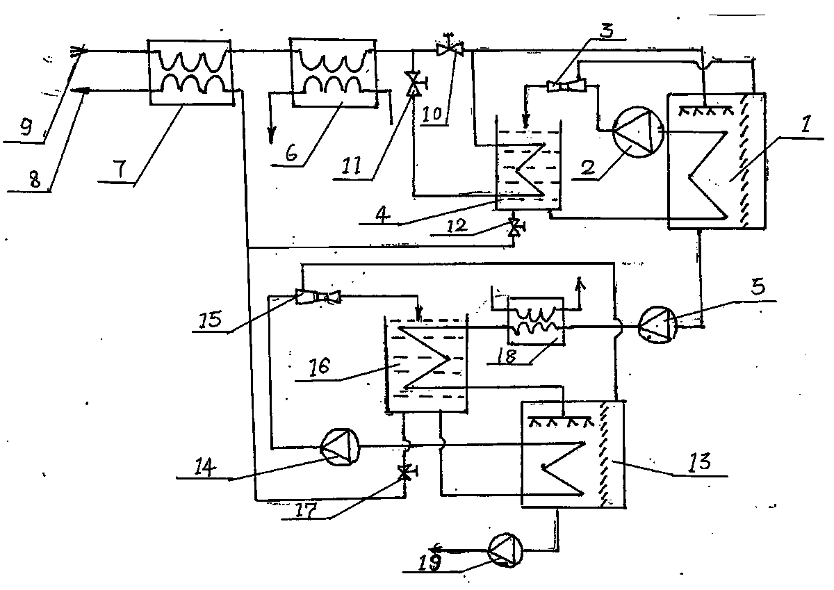
[0041] The difference between the device in this embodiment and the device in Embodiment 1 is that it also includes at least one recirculation evaporation concentration system, and the output end of the primary brine discharge pump 5 is connected to the recirculation evaporation concentration system.
[0042] In this embodiment, a recirculation evaporation concentration system is taken as an example for illustration.
[0043] refer to figure 2, the recirculation evaporative concentration system includes a fourth heat exchanger 18, the output end of the primary concentrated brine discharge pump 5 is connected to the inlet end of the fourth heat exchanger 18 through a pipeline, and the outlet end of the fourth heat exchanger 18 is connected through a pipeline Link to the inlet end of the fifth heat exchanger placed in the second fresh water circulation tank 16, the outlet end of the fifth heat exchanger is connected to the second evaporator 13 through a pipeline, and the vacuum...
Embodiment 3
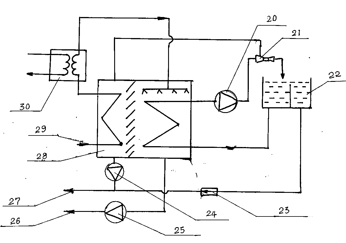
[0052] The difference between the device in this embodiment and the device in Embodiment 1 is that the first evaporator is replaced by a third evaporator 28 with a built-in condenser.
[0053] In this embodiment, a condenser is arranged in the third evaporator 28, the inlet end of the condenser in the third evaporator 28 is the inflow end of seawater, and the outlet end of the condenser in the third evaporator 28 is connected to the heater 30 through a pipeline. The inlet port of the third evaporator 28 is connected with the condensed water suction pump 24 below the condenser, and the outlet end of the heater 30 is connected to the third evaporator 28 through a pipeline, and the third evaporator 28 is connected to the circulation pump through a pipeline. 20 is connected to the inlet end, and the outlet end of the circulation pump 20 is connected to the inlet end of the third condensing injector 21 through the pipeline, and the outlet end of the third condensing injector 21 is p...
PUM
 Abstract
Description
Claims
Application Information