High pressure common rail system control method and device

A technology of a high-pressure common rail system and a control method, which is applied to electrical control, engine control, fuel injection control, etc., can solve problems such as the failure of the engine to work normally and the inability of the high-pressure common rail system to achieve effective control.

Active Publication Date: 2014-03-26
WEICHAI POWER CO LTD
View PDF4 Cites 12 Cited by
  • Summary
  • Abstract
  • Description
  • Claims
  • Application Information

AI Technical Summary

Problems solved by technology

[0006] When any one of the camshaft sensor and the crankshaft speed sensor is working abnormally, the high

Method used


Image

  • High pressure common rail system control method and device
  • High pressure common rail system control method and device

Examples


Embodiment 1

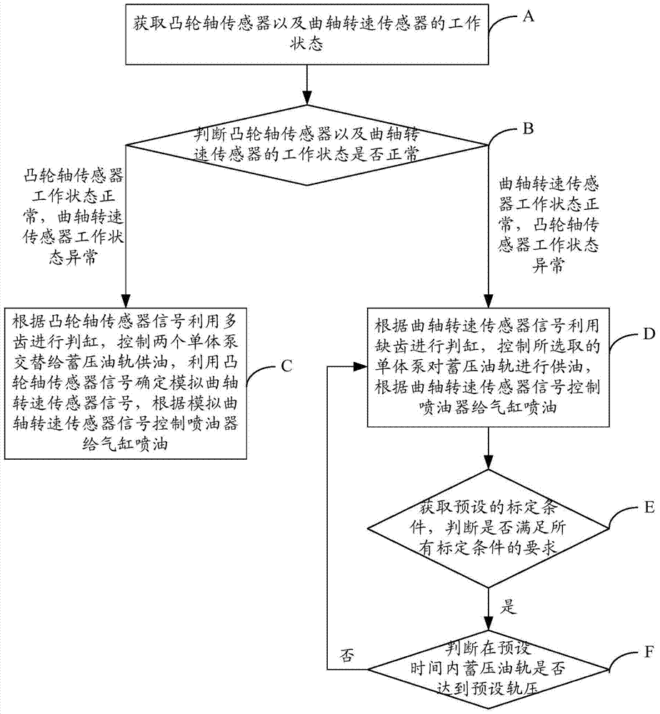
[0054] figure 1 It is a flow chart of Embodiment 1 of a high-pressure common rail system control method of the present invention, and the method includes:

[0055] Step A: Obtain the working status of the camshaft sensor and the crankshaft speed sensor.

[0056] The control system of the high-pressure common rail system is connected with the camshaft sensor and the crankshaft speed sensor. When it is necessary to inject fuel to the cylinder of the engine of the vehicle, the working status of the camshaft sensor and the crankshaft speed sensor is obtained.

[0057] When the camshaft sensor is working normally, the high pressure common rail system can obtain the sensing signal of the camshaft sensor, and the high pressure common rail system can control the two unit pumps to alternately supply oil to the accumulator rail according to the signal of the camshaft sensor.

[0058] The engine has 6 cylinders, and the camshaft has 7 teeth in total. Among them, one cylinder corresponds...

Embodiment 2

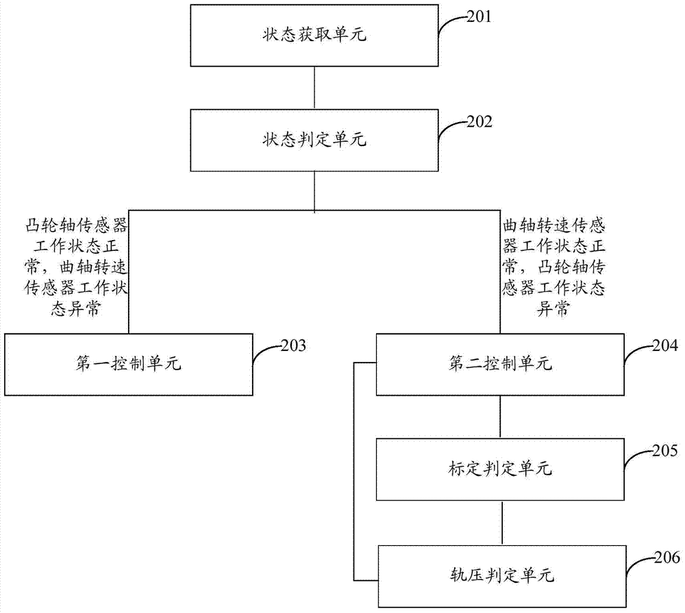
[0091] figure 2 It is a structural schematic diagram of Embodiment 2 of a high-pressure common rail system control device of the present invention, which is a device corresponding to the method protected by Embodiment 1. The device includes:

[0092] The state obtaining unit 201 is used to obtain the working states of the camshaft sensor and the crankshaft speed sensor.

[0093] State judging unit 202, is used for judging whether the working state of camshaft sensor and crankshaft speed sensor is normal, when the working state of camshaft sensor is normal, when the working state of crankshaft speed sensor is abnormal, enter the first control unit 203; When the working state of crankshaft speed sensor If it is normal, if the camshaft sensor is abnormal, enter the second control unit 204 .

[0094] The first control unit 203 is used to judge the cylinder by using multiple teeth according to the camshaft sensor signal, control the two unit pumps to alternately supply oil to the...


PUM


Abstract

The invention provides a high pressure common rail system control method and device. When a cam shaft sensor is in a normal working state and a crank shaft rotating speed sensor is in an abnormal working state, a signal of the crank rotating speed sensor is determined and simulated through a signal of the cam shaft sensor so that an oil sprayer can be controlled to spray oil to an air cylinder. When the crank shaft rotating speed sensor is in a normal working state and the cam shaft sensor is in an abnormal working state, the air cylinder is judged through missing teeth according to the signal of the crank shaft rotating speed sensor, and a monoblock pump is randomly selected to supply oil to a pressure accumulation oil rail. If preset rail pressure is reached within a preset time period, it is proved that the monoblock pump is correctly selected, and if preset rail pressure is not reached within the preset time period, another monoblock pump needs to be selected again to set up rail pressure. When one of the cam shaft sensor and the crank shaft rotating speed sensor is abnormal, a high pressure common rail system can be effectively controlled to supply oil to the monoblock pump and spray oil to an oil spraying nozzle through the signal of one sensor, and normal work of an engine is ensured.

Description

technical field [0001] The invention relates to the technical field of automatic control, in particular to a control method and device for a high-pressure common rail system. Background technique [0002] In order to better protect the environment and realize the sustainable development strategy, the National IV and the National V have strict regulations on the emission of particulate matter from vehicle exhaust. At present, commonly used electronically controlled engines mainly use the common rail fuel system of the plunger pump to supply fuel to the accumulator fuel rail and drive the fuel injector for fuel injection. Among them, the main form of plunger pump is flow control type or fuel supply timing control type, and the fuel supply timing control type plunger pump is mainly a single pump. [0003] In the unit pump common rail system, the camshaft with three symmetrical peaches is connected to the plungers of two electronically controlled unit pumps (EUP) for oil suctio...

Claims


Application Information

Patent Timeline
IPC IPC(8): F02D41/22F02D41/38
Inventor 贾楠刘栋冯杰孙涛
Owner WEICHAI POWER CO LTD
Why Eureka
Try Eureka