Combustion control system and method of industrial furnace

A technology for industrial furnaces and control systems, which is applied in the direction of combustion methods, combustion control, and fuel supply adjustment. Explosion accidents, the effect of high detection accuracy

Active Publication Date: 2014-03-26
FOCUSED PHOTONICS
4 Cites 19 Cited by

AI-Extracted Technical Summary

Problems solved by technology

[0006] 1. Due to the large volume of the heating furnace, the temperature response lags greatly and the temperature adjustment is slow;
[0008] 3. It is impossible to obtain the oxygen and carbon monoxide concentration in each section of the heating furnace in real time and continuously, and it is impossible to determine the actual air consumption coefficient in each section of the heating furnace, that is, it is impossible to determine whether each section of the heating furnace is in the best combustion state;
[0009] 4. Since the combustion situation in the heating furnace cannot be accurately known, the actual air consu...

Abstract

The invention provides a combustion control system and method of an industrial furnace. The combustion control system of the industrial furnace comprises a laser spectrum detection device, a combustion control device, an oxidation burning loss detection device, a comparison device and a computing device, wherein the laser spectrum detection device is used for detecting the content of gas in the industrial furnace, the laser spectrum detection device comprises a laser, a detector and an analysis module, the combustion control device is used for optimizing and adjusting the combustion conditions in the industrial furnace according to data transmitted by the laser spectrum detection device, the oxidation burning loss detection device is used for detecting oxidation burning loss of workpieces which pass through the industrial furnace, and transmitting the detection result to the comparison device, the comparison device is used for obtaining the comparison result according to the received detection result and the original oxidation burning loss conditions, and transmitting the comparison result to the computing device, and the computing device is used for obtaining the combustion control result of the industrial furnace according to the received comparison result. The combustion control system and method of the industrial furnace have the advantages that detection accuracy is high, the detection speed is high, the cost is low, and energy is saved.

Application Domain

Technology Topic

Product gasIndustrial furnace +4

Image

  • Combustion control system and method of industrial furnace
  • Combustion control system and method of industrial furnace
  • Combustion control system and method of industrial furnace

Examples

  • Experimental program(5)

Example Embodiment

[0088] Example 1:
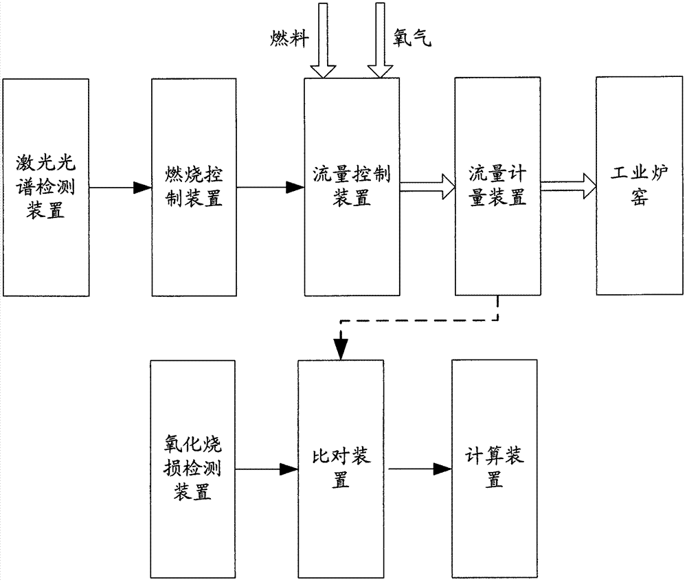
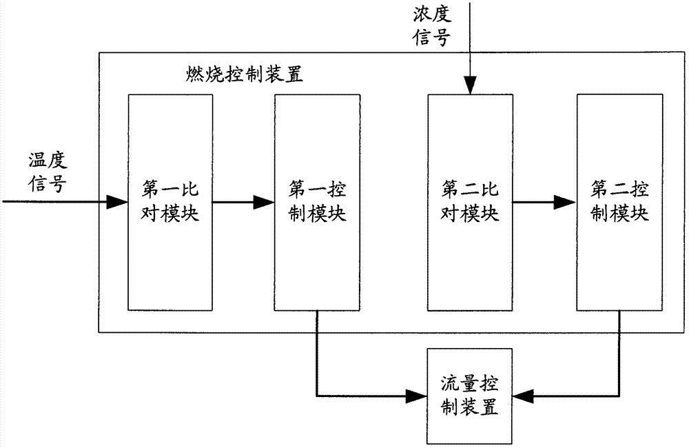
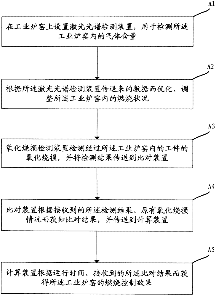
[0089] figure 1 The structure diagram of the combustion control system of the industrial furnace kiln according to the embodiment of the present invention is schematically presented, such as figure 1 As shown, the combustion control system of the industrial kiln includes:
[0090] A laser spectrum detection device, the laser spectrum detection device is arranged on the industrial furnace, and is used to detect the gas content in the industrial furnace, such as the content of oxygen and carbon monoxide; the laser spectrum detection device includes a laser, a detector and analysis modules. The laser and the detector can be installed on opposite sides of the industrial furnace respectively, so that the measurement light path passes through the gas in the industrial furnace; the laser and the detector can also be installed on one side, and the light reflection part can be installed on the opposite other side. side, so that the measuring light passes through the gas in the industrial furnace twice.
[0091] A combustion control device, which is used for optimizing and adjusting the combustion conditions in the industrial furnace according to the data transmitted by the laser spectrum detection device; specifically, the oxygen, The parameters of gas content such as carbon monoxide reflect the combustion conditions in the industrial furnace. The control device adjusts the flow of oxygen, carbon monoxide and other gases input into the industrial furnace according to the measured combustion conditions, or the amount of other types of fuels, such as oil, Therefore, the combustion in each section of the industrial kiln is in an optimal state, on the one hand, the fuel consumption is reduced, and on the other hand, the oxidative burning loss of the heated workpiece caused by excessive oxygen is also reduced.
[0092] The oxidative burnout detection device is used to detect the oxidative burnout of the workpiece passing through the industrial furnace and kiln, and transmit the detection result to the comparison device; There are technologies, which will not be repeated here.
[0093] A comparison device, the comparison device is used to obtain the comparison result according to the received detection result and the original oxidative burnout condition, and transmit the comparison result to the computing device; the comparison device can be realized by software or circuit.
[0094] A computing device, the computing device is configured to obtain the combustion control effect of the industrial furnace according to the operation time of the control system and the received comparison result, that is, the reduction of oxidation burning loss after the combustion control is adopted , the reduction can be converted into the economic benefit of the control system owner unit, and the supplier of the control system can extract a part of the economic benefit as a profit.
[0095] In order to more effectively detect the gas content or temperature in the central area of ​​the industrial furnace to overcome the inherent shortcomings of the zirconia sensor, preferably, on the measurement optical path formed by the laser spectrum detection device, the unit optical path in the industrial furnace is The gas in the central region (higher temperature) absorbs the measurement light more strongly than the edge region (lower temperature), so that the absorption in the edge region is negligible.
[0096] In order to truly reflect the combustion condition in the industrial furnace and use it for feedback control, preferably, the optical path for detecting gas content formed by the laser spectrum detection device is 10-50 cm above the burner in the industrial furnace. The area is the flame burning area, or between the heating workpiece and the burner, to accurately detect the combustion atmosphere near the workpiece.
[0097] In order to measure the combustion temperature in the industrial kiln accurately, quickly and at low cost, optionally, the laser spectrum detection device is also used to detect the temperature in the industrial kiln, and the specific measurement method is existing in the art. technology, which will not be repeated here.
[0098] figure 2 A schematic diagram of the structure of the combustion control device according to the embodiment of the present invention is given, such as figure 2 As shown, the combustion control device further includes:
[0099] The first comparison module (circuit or software), the first comparison module is used to compare the temperature set value (when the combustion in the industrial furnace is in an optimal state) and the temperature measured value in the industrial furnace , the comparison situation is sent to the first control module;
[0100] A first control module (circuit or software) for controlling the flow of fuel and oxygen into the industrial kiln according to the comparison:
[0101] If the measured temperature value is higher than the set value, reduce the fuel (such as carbon monoxide, oil, coal and other gaseous, liquid, solid fuel) flow and oxygen flow, such as adjusting the gas flow control device, such as butterfly valve;
[0102] If the measured temperature value is lower than the set value, increase the fuel flow and oxygen flow, such as increasing the opening of the valve on the fuel pipeline.
[0103] According to the above control system, optionally, the combustion control device further comprises:
[0104] The second comparison module (circuit or software), the second comparison module is used to compare the gas content setting value (when the combustion in the industrial furnace is in an optimal state), the gas content sent by the laser spectrum detection device The measured value of gas content, the comparison status is sent to the second control module;
[0105] A second control module (circuit or software) for controlling the flow of fuel or oxygen into the industrial kiln based on the comparison conditions:
[0106] If the measured value of the fuel content is higher than the set value, increase the oxygen flow, such as adjusting the valve that controls the air flow;
[0107] If the measured value of oxygen content is higher than the set value, reduce the oxygen flow.
[0108] In order to effectively measure the temperature in the industrial furnace, preferably, the optical path for detecting the temperature formed by the laser spectrum detection device is 2-20 cm above the workpiece in the industrial furnace.
[0109]In order to further obtain the combustion control effect, the flow meter measures the flow of fuel and oxygen, and transmits it to the comparison device. The comparison device obtains the fuel and gas saved compared with the existing control method and transmits it to the calculation device, the calculation device calculates the economic benefits obtained by adopting the above-mentioned combustion control system and method according to the amount of fuel and gas saved, the reduction of oxidative burning loss, and the operation time, and the combustion control system supplier extracts the economic benefits from the above Part of it is used as income, and the extraction proportion is agreed by the owner unit and the supplier through the energy-saving renovation agreement in advance.
[0110] In order to avoid the area affected by air leakage at the steel inlet, preferably, the distance from the laser spectrum detection device to the steel inlet side of the preheating section of the industrial kiln is at least 1.5m.
[0111] In order to avoid the area affected by air leakage at the tapping port, preferably, the distance from the laser spectrum detection device to the tapping side of the soaking section of the industrial furnace is at least 1 m.
[0112] image 3 A combustion control method of an industrial kiln is schematically given, that is, the working method of the combustion control system of the above-mentioned industrial kiln, such as image 3 As shown, the combustion control method of the industrial kiln comprises the following steps:
[0113] (A1) A laser spectrum detection device is provided on the industrial furnace to detect the gas content in the industrial furnace;
[0114] (A2) optimizing and adjusting the combustion conditions in the industrial furnace according to the data transmitted by the laser spectrum detection device;
[0115] (A3) The oxidative burnout detection device detects the oxidative burnout of the workpiece in the industrial furnace, and transmits the detection result to the comparison device;
[0116] (A4) The comparison device obtains the comparison result according to the received detection result and the original oxidation burnout condition, and transmits it to the computing device;
[0117] (A5) The computing device obtains the combustion control effect of the industrial kiln according to the running time and the received comparison result.
[0118] Optionally, the oxidative burnout detection device adopts the weight-specific surface area similarity method or the iron oxide scale weighing method or the billet weighing method or the thickness measurement method. These detection methods are all in the prior art and will not be repeated here.
[0119] In order to make the combustion in the industrial kiln in an optimal state, preferably, the soaking section and the heating section of the industrial kiln are reducing atmospheres, and further, the preheating section of the industrial kiln is partially reducing Atmosphere or partially oxidizing atmosphere or neutral atmosphere.
[0120] In order to effectively measure the temperature in the industrial furnace, optionally, the laser spectrum detection device is also used to detect the temperature in the industrial furnace.
[0121] In order to accurately and quickly feedback control the combustion conditions in the industrial kiln, so that the combustion is in an optimal state, optionally, step (A2) further includes the following steps:
[0122] (B1) The first comparison module (software or circuit) is used to compare the temperature set value (when the combustion in the industrial furnace is in an optimal state) and the measured temperature value in the industrial furnace, and transmit the comparison situation to the first control module;
[0123] (B2) The first control module (software or circuit) controls the flow of fuel and/or oxygen into the industrial kiln according to the comparison:
[0124] If the measured temperature value is higher than the set value, reduce the fuel flow rate and/or the oxygen flow rate, and return to step (B1);
[0125] If the measured temperature value is lower than the set value, increase the fuel flow rate and/or the oxygen flow rate, and return to step (B1);
[0126] If the measured temperature value is equal to the set value, go to the next step.
[0127] In order to better optimize the combustion in the industrial kiln, optionally, step (A2) further comprises the following steps:
[0128] (C1) The second comparison module (software or circuit) compares the set value of the gas content (when the combustion in the industrial furnace is in an optimal state), the measured value of the content transmitted by the laser spectrum detection device, and the comparison status sent to the second control module;
[0129] (C2) The second control module (software or circuit) controls the flow of fuel or oxygen into the industrial kiln according to the comparison condition:
[0130] If the measured value of the fuel content is higher than the set value, increase the oxygen flow rate and return to step (B1);
[0131] If the measured value of the oxygen content is higher than the set value, reduce the oxygen flow and return to step (B1);
[0132] If the gas content meets the set value, go to the next step.
[0133] According to the combustion control method of the above-mentioned industrial furnace, optionally, step (A2) further comprises the following steps:
[0134] (D1) the third comparison module compares the set value of oxygen content and the measured value of oxygen content sent by the laser spectrum detection device, and the comparison status is sent to the third control module;
[0135] (D2) The third control module adjusts the amount of oxygen delivered to the industrial kiln, so that the measured value of the oxygen content in the industrial kiln reaches the set value.
[0136] According to the combustion control method of the above-mentioned industrial furnace, optionally, step (A2) further comprises the following steps:
[0137] (D3) Determine whether the measured value of the fuel content sent by the laser spectrum detection device exceeds the standard:
[0138] If the measured value of the fuel content exceeds the standard, adjust the set value of the oxygen content, and return to step (D1);
[0139] If the measured value of fuel content does not exceed the standard, the current set value of oxygen content will be maintained.
[0140] In order to better measure the combustion control effect, optionally, in the above control process, the flow meter measures the flow of fuel and air input into the heating furnace, and transmits it to the comparison device (there is the gas flow consumed to heat the same workpiece in the past) , so as to obtain the amount of fuel and gas saved compared with the existing control method, and send it to the computing device, and the computing device calculates the amount of fuel and gas saved, the reduction of oxidative burning loss, and the running time. The economic benefits obtained by the combustion control system and method, the combustion control system supplier extracts part of the economic benefits as revenue, and the extraction ratio is agreed by the owner and the supplier through a prior energy-saving renovation agreement.
[0141] In order to further enhance the combustion control effect of the industrial furnace, the combustion conditions of the heating section, preheating section and soaking section in the industrial furnace are independently controlled.
[0142] The benefits achieved by the control system and control method for an industrial furnace according to Embodiment 1 of the present invention are that the gas content and temperature measured by the adopted laser spectrum detection device accurately and rapidly reflect the combustion conditions in the industrial furnace, while the control The introduction of the method makes the combustion in the industrial furnace in the best state, so that the fuel and gas consumption is in the best state, and the oxidation burning loss of the heated workpiece is also at a low level, which greatly improves the economic efficiency of the owner and the supplier. 's earnings.

Example Embodiment

[0143] Example 2:
[0144] An application example of the combustion control system and control method of an industrial furnace according to Embodiment 1 of the present invention in a steel rolling heating furnace.
[0145] Figure 4 , 5 The horizontal and vertical installation diagrams of the laser spectrum detection device of this application example are given respectively, as shown in the figure. Figure 4 , 5 As shown in the figure, the heating furnace is divided into a preheating section, a heating section and a soaking section. The installation position of the laser spectrum detection device is as follows: in terms of height, it is 10-50 cm above the upper burner of each section; at this height position, the installation, It is easy to maintain and has a good optical path; in the horizontal direction, the preheating section: avoid the area affected by air leakage at the steel inlet (2.2m from the steel inlet side), and take the center of the section slightly to the center of the two burners in the heating section; the heating section : Take the center position of the section; soaking section: avoid the area affected by the air leakage of the tapping port (2m away from the tapping side), and take the center of the section slightly to the center of the two burners of the heating section. The measured gas (oxygen and carbon monoxide) concentration is the average concentration in the width direction of the heating furnace, the measured optical path is the width of the heating furnace, the width is generally ≥ 6 meters, and the concentration at several local points near the furnace wall fluctuates irregularly. It has almost no effect on the average concentration of components in the furnace, the average concentration can truly reflect the atmosphere environment in the furnace, and the measured value can be used for automatic chain control.
[0146] During the working process of the above control system:
[0147] The original DCS/PLC of the owner of the control system sets the heating target temperature and the upper and lower limits of the heating target temperature according to the billet type, presets the air-fuel ratio, and the laser combustion control system (FOCS) sets the upper and lower limits of oxygen and carbon monoxide concentrations.
[0148] The air consumption coefficient of the soaking section is set to be 0.9 to 1.0; the air consumption coefficient of the heating section is 0.95 to 1.05; the air consumption coefficient of the preheating section is set to 1.05 to 1.15; That is, under high temperature and low oxygen, the oxidative burning loss of the billet can be greatly reduced; the preheating section is a weak oxidizing atmosphere (with oxygen remaining), and the remaining fuel in the soaking section and the heating section and the remaining oxygen in the preheating section are in the preheating section. The mixture is fully burned to ensure that the fuel is not wasted.
[0149] The specific combustion control methods are:
[0150] (B1) The first comparison module compares the temperature setting value and the temperature value in the industrial furnace measured in a conventional manner, and the comparison result is transmitted to the first control module;
[0151] (B2) The first control module feeds back the combustion conditions in each section of the heating furnace according to the comparison result:
[0152] 1. If the measured temperature meets the set requirements: the original DCS/PLC system of the owner unit does not adjust the gas flow, and the laser spectrum detection device transmits the measured oxygen and carbon monoxide concentrations to the second comparison module;
[0153] The second comparison module compares the concentration setting value and the measured gas concentration value, and transmits the result to the second control module;
[0154] The second control module feedback-controls the gas flow input into each section of the heating furnace according to the received results:
[0155] If the oxygen concentration exceeds the set upper limit, reduce the air flow so that the oxygen content is lower than the set value upper limit, and return to step (B1);
[0156] If the carbon monoxide content exceeds the set upper limit, increase the air flow so that the carbon monoxide content is lower than the set value upper limit, and return to step (B1);
[0157] If the gas concentration value matches the set value, go to the next step.
[0158] 2. If the measured temperature rises above the set upper limit: the original DCS/PLC system of the owner unit reduces the gas flow, and the FOCS system tracks the gas flow adjustment to reduce the air flow (the air-fuel ratio is the preset value), and returns to step (B1).
[0159] 3. The measured temperature drop exceeds the set lower limit: the original DCS/PLC system of the owner increases the gas flow, and the FOCS system tracks the set value of the gas flow to adjust the air flow (the air-fuel ratio is the preset value, the linkage is set in the system, and the air is adjusted first) , and return to step (B1).
[0160] The above control methods can be performed independently in each section of the heating furnace.
[0161] A butterfly valve is used to control the flow of gas and air respectively, the input end is connected to the first control module and the second control module, a flow meter is used to measure the flow of gas and air respectively, and the output end is connected to a comparison device. Compared with the existing control method, the comparison device obtains the saving amount of gas and air, and the calculating device obtains the economic benefit after adopting the combustion control system and method according to the saving amount and the reduction amount of oxidation burning loss, and according to the calculation device. The energy-saving sharing agreement signed in advance by the owner unit and the control system supplier will obtain the benefits that the supplier should receive.

Example Embodiment

[0162] Example 3:
[0163] An application example of the combustion control system and control method of an industrial furnace according to Embodiment 1 of the present invention in a steel rolling heating furnace.
[0164] In this application example, the heating furnace is divided into a preheating section, a heating section and a soaking section. The installation position of the first set of laser spectrum detection device is specifically: in terms of height, it is between the burners of each section and the workpiece; this height In terms of location, installation and maintenance are convenient, and the optical path is good, which can better detect the combustion atmosphere of the workpiece accessories; in the horizontal direction, the preheating section: avoid the area affected by air leakage from the steel inlet (2m from the steel inlet side), and take the center of the section Slightly biased toward the center of the two burners in the heating section; heating section: take the center position of the section; soaking section: avoid the area affected by air leakage from the tapping port (1.8m from the tapping side), and take the center of the section slightly biased towards the two sides of the heating section. The burner center position. The measured gas (oxygen and carbon monoxide) concentration is the average concentration in the width direction of the heating furnace, the measured optical path is the width of the heating furnace, the width is generally ≥ 6 meters, and the concentration at several local points near the furnace wall fluctuates irregularly. It has almost no effect on the average concentration of components in the furnace, the average concentration can truly reflect the atmosphere environment in the furnace, and the measured value can be used for automatic chain control.
[0165] The optical path for temperature detection formed by the second set of laser spectrum detection device is 2-20cm above the workpiece in the industrial furnace.
[0166] During the working process of the above control system:
[0167] The original DCS/PLC of the owner unit sets the heating target temperature and the upper and lower limits of the heating target temperature according to the billet type, sets the preset air-fuel ratio, and the laser combustion control system (FOCS) sets the upper and lower limits of oxygen and carbon monoxide concentrations.
[0168] The air consumption coefficient of the soaking section is set to be 0.9 to 1.0; the air consumption coefficient of the heating section is 0.95 to 1.05; the air consumption coefficient of the preheating section is set to 1.05 to 1.15; That is, under high temperature and low oxygen, the oxidative burning loss of the billet can be greatly reduced; the preheating section is a weak oxidizing atmosphere (with oxygen remaining), and the remaining fuel in the soaking section and the heating section and the remaining oxygen in the preheating section are in the preheating section. The mixture is fully burned to ensure that the fuel is not wasted.
[0169] The specific combustion control methods are:
[0170] (B1) The first comparison module compares the temperature setting value and the temperature value measured by the laser spectrum detection device, and the comparison result is transmitted to the first control module;
[0171] (B2) The first control module feeds back the combustion conditions in each section of the heating furnace according to the comparison result:
[0172] 1. If the measured temperature meets the set requirements: the FOCS system does not adjust the gas flow, and the laser spectrum detection device transmits the measured oxygen and carbon monoxide concentrations to the second comparison module;
[0173] The second comparison module compares the concentration setting value and the measured gas concentration value, and transmits the result to the second control module;
[0174] The second control module feedback-controls the gas flow input into each section of the heating furnace according to the received results:
[0175] If the oxygen concentration exceeds the set upper limit, reduce the air flow so that the oxygen content is lower than the set value upper limit, and return to step (B1);
[0176] If the carbon monoxide content exceeds the set upper limit, increase the air flow so that the carbon monoxide content is lower than the set value upper limit, and return to step (B1);
[0177] If the gas concentration value matches the set value, go to the next step.
[0178] 2. If the measured temperature rises above the set upper limit: the FOCS system automatically reduces the flow of gas and oxygen (the air-fuel ratio is the preset value), and returns to step (B1).
[0179] 3. The measured temperature drops beyond the set lower limit: the FOCS system automatically increases the flow of gas and oxygen (the air-fuel ratio is the preset value, and the linkage is set in the system, first increase the oxygen flow, then increase the gas flow), and return to step (B1) .
[0180] The above control methods are performed independently in each section of the heating furnace.
[0181] A butterfly valve is used to control the flow of gas and air respectively, the input end is connected to the first control module and the second control module, a flow meter is used to measure the flow of gas and air respectively, and the output end is connected to a comparison device. Compared with the existing control method, the comparison device obtains the saving amount of gas and air, and the calculating device obtains the economic benefit after adopting the combustion control system and method according to the saving amount and the reduction amount of oxidation burning loss, and according to the calculation device. The energy-saving sharing agreement signed in advance by the owner unit and the control system supplier will obtain the benefits that the supplier should receive.
[0182] The field experiment results show that: through the above combustion control, the accurate control of the atmosphere in each section of the heating furnace can be achieved, so that the air consumption coefficient is controlled within a reasonable range, the thermal efficiency utilization is greatly improved, and the heating temperature fluctuation amplitude is greatly reduced. Reduced fuel consumption per ton of billet.

PUM

no PUM

Description & Claims & Application Information

We can also present the details of the Description, Claims and Application information to help users get a comprehensive understanding of the technical details of the patent, such as background art, summary of invention, brief description of drawings, description of embodiments, and other original content. On the other hand, users can also determine the specific scope of protection of the technology through the list of claims; as well as understand the changes in the life cycle of the technology with the presentation of the patent timeline. Login to view more.

Similar technology patents

Classification and recommendation of technical efficacy words

  • Save fuel
  • Good energy saving effect

Auxiliary power device for refrigerated trucks

InactiveUS20070052241A1Prevent over-currentSave fuelAir-treating devicesRefrigerated goods vehicleTruckDriver/operator
Owner:PACY DAVID H

Floor type air conditioner

Owner:GREE ELECTRIC APPLIANCES INC
Why Eureka
Try Eureka